


11-3
Catalyst 2950 Desktop Switch Software Configuration Guide
78-14982-01
Chapter 11 Configuring STP
Understanding Spanning-Tree Features
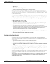
• Message age
• The identifier of the sending interface
• Values for the hello, forward delay, and max-age protocol timers
When a switch receives a configuration BPDU that contains superior information (lower bridge ID,
lower path cost, and so forth), it stores the information for that port. If this BPDU is received on the root
port of the switch, the switch also forwards it with an updated message to all attached LANs for which
it is the designated switch.
If a switch receives a configuration BPDU that contains inferior information to that currently stored for
that port, it discards the BPDU. If the switch is a designated switch for the LAN from which the inferior
BPDU was received, it sends that LAN a BPDU containing the up-to-date information stored for that
port. In this way, inferior information is discarded, and superior information is propagated on the
network.
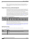
A BPDU exchange results in these actions:
• One switch is elected as the root switch.
• A root port is selected for each switch (except the root switch). This port provides the best path
(lowest cost) when the switch forwards packets to the root switch.
• The shortest distance to the root switch is calculated for each switch based on the path cost.
• A designated switch for each LAN segment is selected. The designated switch incurs the lowest path
cost when forwarding packets from that LAN to the root switch. The port through which the
designated switch is attached to the LAN is called the designated port.
• Interfaces included in the spanning-tree instance are selected. Root ports and designated ports are
put in the forwarding state.
• All interfaces not included in the spanning tree are blocked.
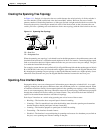
Election of the Root Switch
All switches in the Layer 2 network participating in spanning tree gather information about other
switches in the network through an exchange of BPDU data messages. This exchange of messages results
in these actions:
• The election of a unique root switch for each spanning-tree instance
• The election of a designated switch for every switched LAN segment
• The removal of loops in the switched network by blocking Layer 2 interfaces connected to redundant
links
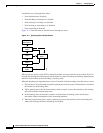
For each VLAN, the switch with the highest switch priority (the lowest numerical priority value) is
elected as the root switch. If all switches are configured with the default priority (32768), the switch with
the lowest MAC address in the VLAN becomes the root switch. The switch priority value occupies the
most significant bits of the bridge ID.
When you change the switch priority value, you change the probability that the switch will be elected as
the root switch. Configuring a higher value decreases the probability; a lower value increases the
probability.
The root switch is the logical center of the spanning-tree topology in a switched network. All paths that
are not needed to reach the root switch from anywhere in the switched network are placed in the
spanning-tree blocking mode.