


14-8
Catalyst 2950 Desktop Switch Software Configuration Guide
78-14982-01
Chapter 14 Configuring VLANs
Configuring Normal-Range VLANs
Default Ethernet VLAN Configuration
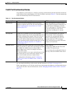
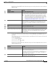
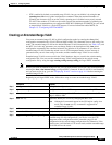
Table 14-2 shows the default configuration for Ethernet VLANs.
Note The switch supports Ethernet interfaces exclusively. Because FDDI and Token Ring VLANs are not
locally supported, you only configure FDDI and Token Ring media-specific characteristics for VTP
global advertisements to other switches.
Creating or Modifying an Ethernet VLAN
Each Ethernet VLAN in the VLAN database has a unique, 4-digit ID that can be a number from 1 to
1001. VLAN IDs 1002 to 1005 are reserved for Token Ring and FDDI VLANs. To create a normal-range
VLAN to be added to the VLAN database, assign a number and name to the VLAN.
Note When the switch is in VTP transparent mode and the EI is installed, you can assign VLAN IDs greater
than 1006, but they are not added to the VLAN database. See the “Configuring Extended-Range
VLANs” section on page 14-12.
For the list of default parameters that are assigned when you add a VLAN, see the “Configuring
Normal-Range VLANs” section on page 14-4.
Table 14-2 Ethernet VLAN Defaults and Ranges
Parameter Default Range
VLAN ID 1 1 to 4094 when the EI is installed and 1 to
1005 when the SI is installed.
Note Extended-range VLANs (VLAN
IDs 1006 to 4094) are not saved in
the VLAN database.
VLAN name VLANxxxx, where xxxx
represents four numeric digits
(including leading zeros) equal
to the VLAN ID number
No range
802.10 SAID 100001 (100000 plus the
VLAN ID)
1–4294967294
MTU size 1500 1500–18190
Translational bridge 1 0 0–1005
Translational bridge 2 0 0–1005
VLAN state active active, suspend