


11-8
Catalyst 2950 Desktop Switch Software Configuration Guide
78-14982-01
Chapter 11 Configuring STP
Understanding Spanning-Tree Features
Disabled State
A Layer 2 interface in the disabled state does not participate in frame forwarding or in the spanning tree.
An interface in the disabled state is nonoperational.
A disabled interface performs as follows:
• Discards frames received on the port
• Discards frames switched from another interface for forwarding
• Does not learn addresses
• Does not receive BPDUs
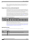
Spanning-Tree Address Management
IEEE 802.1D specifies 17 multicast addresses, ranging from 0x00180C2000000 to 0x0180C2000010, to
be used by different bridge protocols. These addresses are static addresses that cannot be removed.
Regardless of the spanning-tree state, the switch receives but does not forward packets destined for
addresses between 0x0180C2000000 and 0x1080C200000F.
If STP is enabled, the switch CPU receives packets destined for 0x0180C2000000 and
0x0180C2000010. If STP is disabled, the switch forwards those packets as unknown multicast addresses.
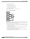
STP and IEEE 802.1Q Trunks
The IEEE 802.1Q standard for VLAN trunks imposes some limitations on the spanning-tree strategy for
a network. The standard requires only one spanning-tree instance for all VLANs allowed on the trunks.
However, in a network of Cisco switches connected through 802.1Q trunks, the switches maintain one
spanning-tree instance for each VLAN allowed on the trunks.
When you connect a Cisco switch to a non-Cisco device through an 802.1Q trunk, the Cisco switch uses
per-VLAN spanning tree+ (PVST+) to provide spanning-tree interoperability. It combines the
spanning-tree instance of the 802.1Q VLAN of the trunk with the spanning-tree instance of the
non-Cisco 802.1Q switch.
However, all PVST+ information is maintained by Cisco switches separated by a cloud of
non-Cisco 802.1Q switches. The non-Cisco 802.1Q cloud separating the Cisco switches is treated as a
single trunk link between the switches.
The external spanning-tree behavior on access ports and trunk ports is not affected by PVST+.
For more information on 802.1Q trunks, see Chapter 14, “Configuring VLANs.”
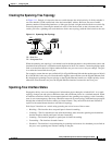
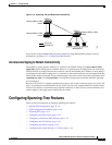
Spanning Tree and Redundant Connectivity
You can create a redundant backbone with spanning tree by connecting two switch interfaces to another
device or to two different devices. Spanning tree automatically disables one interface but enables it if
the other one fails, as shown in Figure 11-3. If one link is high-speed and the other is low-speed, the
low-speed link is always disabled. If the speeds are the same, the port priority and port ID are added
together, and spanning tree disables the link with the lowest value.