


25-23
Catalyst 2950 Desktop Switch Software Configuration Guide
78-14982-01
Chapter 25 Configuring Network Security with ACLs
Examples for Compiling ACLs
Displaying Access Groups
Note This feature is available only if your switch is running the EI.
You use the ip access-group interface configuration command to apply ACLs to a Layer 3 interface.
When IP is enabled on an interface, you can use the show ip interface interface-id privileged EXEC
command to view the input and output access lists on the interface, as well as other interface
characteristics. If IP is not enabled on the interface, the access lists are not shown.
This example shows how to view all access groups configured for VLAN 1 and for Gigabit Ethernet
interface 0/2:
Switch# show ip interface vlan 1
GigabitEthernet0/2 is up, line protocol is down
Internet address is 10.20.30.1/16
Broadcast address is 255.255.255.255
Address determined by setup command
MTU is 1500 bytes
Helper address is not set
Directed broadcast forwarding is disabled
Outgoing access list is permit Any
Inbound access list is 13
<information truncated>
Switch# show ip interface fastethernet0/9
FastEthernet0/9 is down, line protocol is down
Inbound access list is ip1
The only way to ensure that you can view all configured access groups under all circumstances is to use
the show running-config privileged EXEC command. To display the ACL configuration of a single
interface, use the show running-config interface interface-id command.
This example shows how to display the ACL configuration of Gigabit Ethernet interface 0/1:
Switch# show running-config interface gigabitethernet0/1
Building configuration...
Current configuration :112 bytes
!
interface GigabitEthernet0/1
ip access-group 11 in
snmp trap link-status
no cdp enable
end!
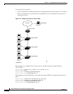
Examples for Compiling ACLs
For detailed information about compiling ACLs, refer to the Security Configuration Guide and the “IP
Services” chapter of the Cisco IOS IP and IP Routing Configuration Guide for IOS Release 12.1.
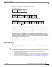
Figure 25-2 shows a small networked office with a stack of switches that are connected to a Cisco router.
A host is connected to the network through the Internet using a WAN link.