


11-5
Catalyst 2950 Desktop Switch Software Configuration Guide
78-14982-01
Chapter 11 Configuring STP
Understanding Spanning-Tree Features
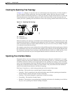
Creating the Spanning-Tree Topology
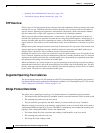
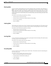
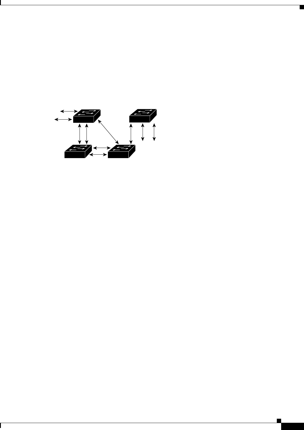
In Figure 11-1, Switch A is elected as the root switch because the switch priority of all the switches is
set to the default (32768) and Switch A has the lowest MAC address. However, because of traffic
patterns, number of forwarding interfaces, or link types, Switch A might not be the ideal root switch. By
increasing the priority (lowering the numerical value) of the ideal switch so that it becomes the root
switch, you force a spanning-tree recalculation to form a new topology with the ideal switch as the root.
Figure 11-1 Spanning-Tree Topology
When the spanning-tree topology is calculated based on default parameters, the path between source and
destination end stations in a switched network might not be ideal. For instance, connecting higher-speed
links to an interface that has a higher number than the root port can cause a root-port change. The goal
is to make the fastest link the root port.
For example, assume that one port on Switch B is a Gigabit Ethernet link and that another port on Switch
B (a 10/100 link) is the root port. Network traffic might be more efficient over the Gigabit Ethernet link.
By changing the spanning-tree port priority on the Gigabit Ethernet interface to a higher priority (lower
numerical value) than the root port, the Gigabit Ethernet interface becomes the new root port.
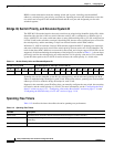
Spanning-Tree Interface States
Propagation delays can occur when protocol information passes through a switched LAN. As a result,
topology changes can take place at different times and at different places in a switched network. When
an interface transitions directly from nonparticipation in the spanning-tree topology to the forwarding
state, it can create temporary data loops. Interfaces must wait for new topology information to propagate
through the switched LAN before starting to forward frames. They must allow the frame lifetime to
expire for forwarded frames that have used the old topology.
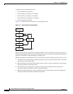
Each Layer 2 interface on a switch using spanning tree exists in one of these states:
• Blocking—The interface does not participate in frame forwarding.
• Listening—The first transitional state after the blocking state when the spanning tree determines
that the interface should participate in frame forwarding.
• Learning—The interface prepares to participate in frame forwarding.
• Forwarding—The interface forwards frames.
• Disabled—The interface is not participating in spanning tree because of a shutdown port, no link on
the port, or no spanning-tree instance running on the port.
43568
DP
DP
RP DP
DP
RP
DP
RP = Root Port
DP = Designated Port
DP
RP
DP
DA
CB