


13-4
Catalyst 2950 Desktop Switch Software Configuration Guide
78-14982-01
Chapter 13 Configuring Optional Spanning-Tree Features
Understanding Optional Spanning-Tree Features
Understanding UplinkFast
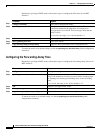
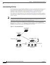
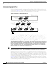
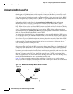
Switches in hierarchical networks can be grouped into backbone switches, distribution switches, and
access switches. Figure 13-2 shows a complex network where distribution switches and access switches
each have at least one redundant link that spanning tree blocks to prevent loops.
Figure 13-2 Switches in a Hierarchical Network
If a switch looses connectivity, it begins using the alternate paths as soon as the spanning tree selects a
new root port. By enabling UplinkFast with the spanning-tree uplinkfast global configuration
command, you can accelerate the choice of a new root port when a link or switch fails or when the
spanning tree reconfigures itself. The root port transitions to the forwarding state immediately without
going through the listening and learning states, as it would with the normal spanning-tree procedures.
The UplinkFast feature is supported only when the switch is running PVST.
When the spanning tree reconfigures the new root port, other interfaces flood the network with multicast
packets, one for each address that was learned on the interface. You can limit these bursts of multicast
traffic by reducing the max-update-rate parameter (the default for this parameter is 150 packets per
second). However, if you enter zero, station-learning frames are not generated, so the spanning-tree
topology converges more slowly after a loss of connectivity.
Note UplinkFast is most useful in wiring-closet switches at the access or edge of the network. It is not
appropriate for backbone devices. This feature might not be useful for other types of applications.
UplinkFast provides fast convergence after a direct link failure and achieves load balancing between
redundant Layer 2 links using uplink groups. An uplink group is a set of Layer 2 interfaces (per VLAN),
only one of which is forwarding at any given time. Specifically, an uplink group consists of the root port
(which is forwarding) and a set of blocked ports, except for self-looping ports. The uplink group provides
an alternate path in case the currently forwarding link fails.
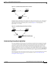
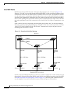
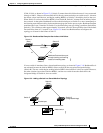
Figure 13-3 shows an example topology with no link failures. Switch A, the root switch, is connected
directly to Switch B over link L1 and to Switch C over link L2. The Layer 2 interface on Switch C that
is connected directly to Switch B is in a blocking state.
2950 2950 2950 2950
Active link
Blocked link
Root bridge
Backbone switches
Distribution switches
Access switches
74623
Catalyst 3550
switches
Catalyst 3550
switches