


6-24
Catalyst 2950 Desktop Switch Software Configuration Guide
78-14982-01
Chapter 6 Clustering Switches
Creating a Switch Cluster
Verifying a Switch Cluster
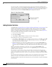
When you finish adding cluster members, follow these steps to verify the cluster:
Step 1 Enter the command switch IP address in the browser Location field (Netscape Communicator) or
Address field (Microsoft Internet Explorer) to access all switches in the cluster.
Step 2 Enter the command-switch password.
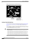
Step 3 Select View > Topology to display the cluster topology and to view link information (see Figure 3-8 on
page 3-11). For complete information about the Topology view, including descriptions of the icons,
links, and colors, see the “Topology View” section on page 3-10.
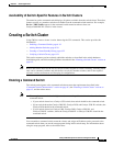
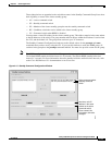
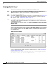
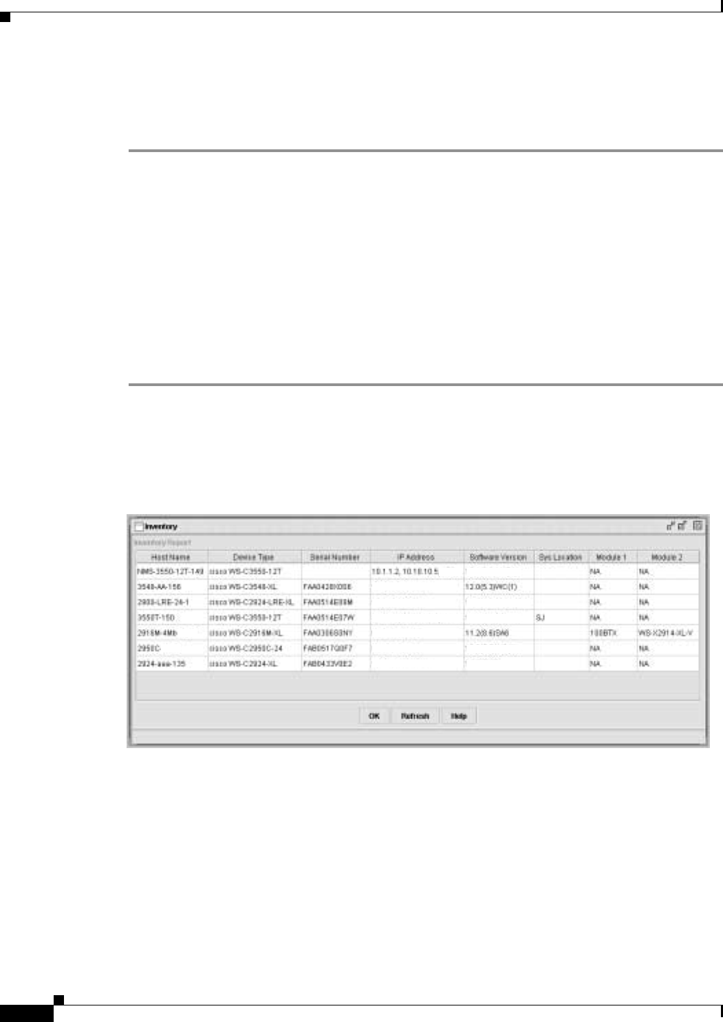
Step 4 Select Reports > Inventory to display an inventory of the switches in the cluster (see Figure 6-14).
The summary includes information such as switch model numbers, serial numbers, software versions,
IP information, and location.
You can also display port and switch statistics from Reports > Port Statistics and Port > Port Settings
> Runtime Status.
Instead of using CMS to verify the cluster, you can use the show cluster members user EXEC command
from the command switch or use the show cluster user EXEC command from the command switch or
from a member switch.
Figure 6-14 Inventory Window
If you lose connectivity with a member switch or if a command switch fails, see the “Using Recovery
Procedures” section on page 28-6.
For more information about creating and managing clusters, refer to the online help. For information
about the cluster commands, refer to the switch command reference.
10.10.10.6
12.1(4)EA1
12.0(5)WC2
12.1(4)EA1
12.1(6)EA2
13.0(5)XU
10.10.10.7
10.1.1.2, 10.10.10.1, 10.
10.10.10.2
10.10.10.3
10.10.10.9
65727