


6-10
Catalyst 2950 Desktop Switch Software Configuration Guide
78-14982-01
Chapter 6 Clustering Switches
Planning a Switch Cluster
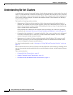
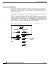
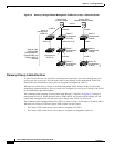
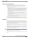
Figure 6-6 Discovery through Different Management VLANs with a Layer 3 Command Switch
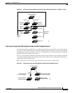
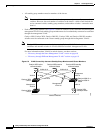
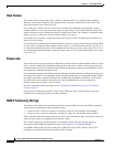
Discovery of Newly Installed Switches
To join a cluster, the new, out-of-the-box switch must be connected to the cluster through one of its
access ports. An access port (AP) carries the traffic of and belongs to the management VLAN. By
default, the new switch and its access ports are assigned to management VLAN 1.
When the new switch joins a cluster, its default management VLAN changes to the VLAN of the
immediately upstream neighbor. The new switch also configures its access port to belong to the VLAN
of the immediately upstream neighbor.
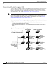
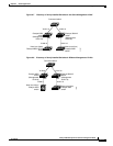
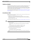
The command switch (running a release earlier than Release 12.1(9)EA1) in Figure 6-7 belongs to
management VLAN 16. When the new Catalyst 2900 LRE XL and Catalyst 2950 switches join the
cluster, their management VLAN and access ports change from VLAN 1 to VLAN 16.
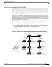
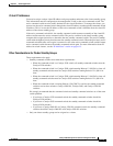
The command switch (running Release 12.1(9)EA1 or later) in Figure 6-8 belongs to VLANs 9 and 16.
When the new Catalyst 3550 and Catalyst 2950 switches join the cluster:
• The Catalyst 3550 switch and its access port are assigned to VLAN 9.
• The Catalyst 2950 switch and its access port are assigned to management VLAN 16.
Si Si
Catalyst 1900,
Catalyst 2820,
Catalyst 2900 XL,
Catalyst 2950, and
Catalyst 3500 XL
switches
VLAN 62
VLAN trunk 4, 62
VLAN 62
VLAN 16
VLAN 9
VLAN 16
VLAN 9
Catalyst 3550
standby command switch
Catalyst 3550
command switch
VLAN 9
Switch 7
(management
VLAN 4)
Switch 9
(management
VLAN 62)
VLAN 4
54983
Switch 3
(management
VLAN 16)
Switch 4
(management
VLAN 16)
Switch 10
(management
VLAN 4)
Switch 8
(management
VLAN 9)
Switch 6
(management
VLAN 9)
Switch 5
(management
VLAN 62)