


12-7
Catalyst 2950 Desktop Switch Software Configuration Guide
78-14982-01
Chapter 12 Configuring RSTP and MSTP
Understanding MSTP
• Propagation—When an RSTP switch receives a TC message from another switch through a
designated or root port, it propagates the topology change to all of its nonedge, edge, designated
ports, and root port (excluding the port on which it is received). The switch starts the TC-while timer
for all such ports and flushes the information learned on them.
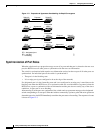
• Protocol migration—For backward compatibility with 802.1D switches, RSTP selectively sends
802.1D configuration BPDUs and TCN BPDUs on a per-port basis.
When a port is initialized, the migrate-delay timer is started (specifies the minimum time during
which RSTP BPDUs are sent), and RSTP BPDUs are sent. While this timer is active, the switch
processes all BPDUs received on that port and ignores the protocol type.
If the switch receives an 802.1D BPDU after the port’s migration-delay timer has expired, it assumes
that it is connected to an 802.1D switch and starts using only 802.1D BPDUs. However, if the RSTP
switch is using 802.1D BPDUs on a port and receives an RSTP BPDU after the timer has expired,
it restarts the timer and starts using RSTP BPDUs on that port.
Understanding MSTP
MSTP, which uses RSTP for rapid convergence, enables VLANs to be grouped into a spanning-tree
instance, with each instance having a spanning-tree topology independent of other spanning-tree
instances. This architecture provides multiple forwarding paths for data traffic, enables load balancing,
and reduces the number of spanning-tree instances required to support a large number of VLANs.
These sections describe how the MSTP works:
• Multiple Spanning-Tree Regions, page 12-7
• IST, CIST, and CST, page 12-8
• Hop Count, page 12-10
For configuration information, see the “Configuring RSTP and MSTP Features” section on page 12-11.
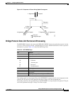
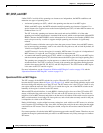
Multiple Spanning-Tree Regions
For switches to participate in multiple spanning-tree (MST) instances, you must consistently configure
the switches with the same MST configuration information. A collection of interconnected switches that
have the same MST configuration comprises an MST region as shown in Figure 12-3 on page 12-9.
The MST configuration determines to which MST region each switch belongs. The configuration
includes the name of the region, the revision number, and the MST instance-to-VLAN assignment map.
You configure the switch for a region by using the spanning-tree mst configuration global
configuration command, after which the switch enters the MST configuration mode. From this mode,
you can map VLANs to an MST instance by using the instance MST configuration command, specify
the region name by using the name MST configuration command, and set the revision number by using
the revision MST configuration command.
A region can have one member or multiple members with the same MST configuration; each member
must be capable of processing RSTP BPDUs. There is no limit to the number of MST regions in a
network, but each region can support up to 16 spanning-tree instances. You can assign a VLAN to only
one spanning-tree instance at a time.