6.1.4 Configure Added Damping
Display Not available
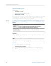
ProLink II ProLink > Configuration > Analog Output > Primary/Secondary Output > AO Added Damp
Field Communicator Configure > Manual Setup > Inputs/Outputs > mA Output 1 > mA Output Settings > PV Added Damping
Configure > Manual Setup > Inputs/Outputs > mA Output 2 > mA Output Settings > PV Added Damping
Overview
Damping is used to smooth out small, rapid fluctuations in process measurement. Damping
Value specifies the time period (in seconds) over which the transmitter will spread changes
in the reported process variable. At the end of the interval, the reported process variable
will reflect 63% of the change in the actual measured value. Added Damping controls the
amount of damping that will be applied to the mA output. It affects the reporting of mA
Output Process Variable through the mA output only. It does not affect the reporting of that
process variable via any other method (e.g., the frequency output or digital
communications), or the value of the process variable used in calculations.
Note
Added Damping is not applied if the mA output is fixed (for example, during loop testing) or if the mA
output is reporting a fault. Added Damping is applied while sensor simulation is active.
Procedure
Set Added Damping to the desired value.
The default value is 0.0 seconds.
When you specify a value for Added Damping, the transmitter automatically rounds the value
down to the nearest valid value.
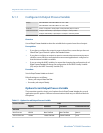
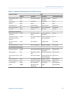
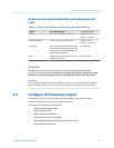
Valid values for Added DampingTable 6-3:
Valid values for Added Damping
0.0, 0.1, 0.3, 0.75, 1.6, 3.3, 6.5, 13.5, 27.5, 55, 110, 220, 440
Interaction between Added Damping and process variable
damping
When mA Output Process Variable is set to a flow variable, density, or temperature, Added
Damping interacts with Flow Damping, Density Damping, or Temperature Damping. If multiple
damping parameters are applicable, the effect of damping the process variable is
calculated first, and the added damping calculation is applied to the result of that
calculation.
Integrate the meter with the control system
Configuration and Use Manual 89


