CAUTION!
Refer to the Micro Motion 9739 MVD Transmitters: Installation Manual for all safety and detailed
wiring information for the transmitter. You are responsible for following all safety and wiring
instructions documented in the transmitter installation manual, plus any additional site
requirements.
You can wire the transmitter to the following sensors:
• ELITE
®
, H-Series, T-Series, and F-Series
• Model D and Model DL
• Model DT (with user-supplied metal junction box with terminal block)
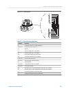
Each wire of the 9-wire cable is inserted into the corresponding terminal at the sensor and
transmitter, matching by color.
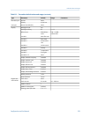
Sensor and transmitter terminal designationsTable E-1:
Wire color Sensor terminal Transmitter terminal Function
Black No connection 0 Drain wires
Brown 1 1 Drive +
Red 2 2 Drive -
Orange 3 3 Temperature -
Yellow 4 4 Temperature return
Green 5 5 Left pickoff +
Blue 6 6 Right pickoff +
Violet 7 7 Temperature +
Gray 8 8 Right pickoff -
White 9 9 Left pickoff -
E.3 Power supply terminals
The power supply terminals on the transmitter must be connected to a power supply.
CAUTION!
Refer to the Micro Motion 9739 MVD Transmitters: Installation Manual for all safety and detailed
wiring information for the 9739 MVD transmitter. You are responsible for following all safety
and wiring instructions documented in the transmitter installation manual, plus any additional
site requirements.
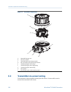
Transmitter components and installation wiring
Configuration and Use Manual 237


