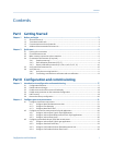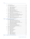
10.25 Check for slug flow (two-phase flow) .........................................................................................185
10.26 Check the drive gain ..................................................................................................................185
10.26.1 Collect drive gain data ................................................................................................186
10.27 Check the pickoff voltage ..........................................................................................................187
10.27.1 Collect pickoff voltage data ........................................................................................188
10.28 Check for electrical shorts ..........................................................................................................188
10.28.1 Check the sensor coils .................................................................................................188
Appendices and reference
Appendix A Using the transmitter display .......................................................................................191
A.1 Components of the transmitter interface ..................................................................................191
A.2 Use the optical switches ............................................................................................................193
A.3 Access and use the display menu system ...................................................................................194
A.3.1 Enter a floating-point value using the display ..............................................................195
A.4 Display codes for process variables ............................................................................................198
A.5 Codes and abbreviations used in display menus ........................................................................199
A.6 Menu maps for the transmitter display ......................................................................................202
Appendix B Using ProLink II with the transmitter ...........................................................................211
B.1 Basic information about ProLink II ..............................................................................................211
B.2 Menu maps for ProLink II ...........................................................................................................212
Appendix C Using the Field Communicator with the transmitter .....................................................217
C.1 Basic information about the Field Communicator ......................................................................217
C.2 Menu maps for the Field Communicator ....................................................................................218
Appendix D Default values and ranges ............................................................................................229
D.1 Default values and ranges ..........................................................................................................229
Appendix E Transmitter components and installation wiring .........................................................235
E.1 Transmitter components ...........................................................................................................235
E.2 Transmitter-to-sensor wiring .....................................................................................................236
E.3 Power supply terminals .............................................................................................................237
E.4 Input/output (I/O) terminals ......................................................................................................238
Index ................................................................................................................................................241
Contents
Configuration and Use Manual v


