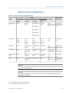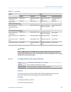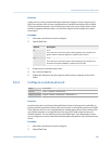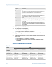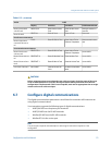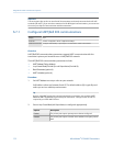
(continued)Table 6-11:
Action Label
Display ProLink II ProLink III Field Communicator
Reset gas standard
volume total
RESET GSVT Reset Gas Std Volume
Total
Reset Gas Std Volume
Total
Reset gas standard vol-
ume total
Reset all totals
RESET ALL Reset All Totals Reset All Totals Reset totals
Petroleum measurement
Reset temperature-
corrected volume to-
tal
TCVOL Reset API Ref Vol Total Reset Volume Total at
Reference Temperature
Reset corrected volume
total
Concentration measurement
Reset CM reference
volume total
RESET STD V Reset CM Ref Vol Total Reset Volume Total at
Reference Temperature
Not available
Reset CM net mass to-
tal
RESET NET M Reset CM Net Mass Total Reset Net Mass Total
Not available
Reset CM net volume
total
RESET NET V Reset CM Net Vol Total Reset Net Volume Total
Not available
Increment CM matrix
INCr CURVE Increment Current CM
Curve
Increment Concentration
Matrix
Not available
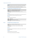
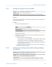
CAUTION!
Before assigning actions to an enhanced event or discrete input, check the status of the event
or the remote input device. If it is ON, all assigned actions will be performed when the new
configuration is implemented. If this is not acceptable, wait until an appropriate time to assign
actions to the event or discrete input.
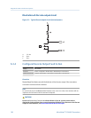
6.4.2
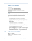
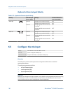
Configure Discrete Input Polarity
Display OFF-LINE MAINT > OFF-LINE CONFG > IO > DI > DI POLAR
ProLink II ProLink > Configuration > Discrete Input > DI1 Polarity
Field Communicator Configure > Manual Setup > Inputs/Outputs > Discrete Input > Polarity
Overview
The discrete input has two states: ON and OFF. Discrete Input Polarity controls how the
transmitter maps the incoming voltage level to the ON and OFF states.
Procedure
Set Discrete Input Polarity as desired.
The default setting is Active Low.
Integrate the meter with the control system
Configuration and Use Manual 105


