


1. Wait approximately 10 seconds for the power-up sequence to complete.
Immediately after power-up, the transmitter runs through diagnostic routines and
checks for error conditions. During the power-up sequence, Alarm A009 is active.
This alarm should clear automatically when the power-up sequence is complete.
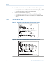
2. Check the status LED on the transmitter.
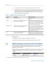
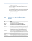
Transmitter status reported by status LEDTable 2-1:
LED state Description Recommendation
Green No alarms are active. Continue with configuration or process meas-
urement.
Yellow One or more low-severity alarms are active,
and have been acknowledged.
A low-severity alarm condition does not affect
measurement accuracy or output behavior.
You can continue with configuration or proc-
ess measurement. If you choose, you can iden-
tify and resolve the alarm condition.
Flashing yellow
(1)
One or more low-severity alarms are active
and have not been acknowledged.
A low-severity alarm condition does not affect
measurement accuracy or output behavior.
You can continue with configuration or proc-
ess measurement. If you choose, you can iden-
tify and resolve the alarm condition. You may
also acknowledge the alarm.
Red One or more high-severity alarms are active,
and have been acknowledged.
A high-severity alarm condition affects meas-
urement accuracy and output behavior. Re-
solve the alarm condition before continuing.
Postrequisites
For information on viewing the list of active alarms, see Section 8.3.
For information on individual alarms and suggested resolutions, see Section 10.2.
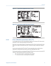
2.3
Make a startup connection to the transmitter
For all configuration tools except the display, you must have an active connection to the
transmitter to configure the transmitter. Follow this procedure to make your first
connection to the transmitter.
Identify the connection type to use, and follow the instructions for that connection type in
the appropriate appendix. Use the default communications parameters shown in the
appendix.
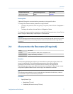
Communications tool
Connection type to use Instructions
ProLink II Modbus/RS-485 Appendix B
(1) If Status LED Blinking is disabled, the LED will show solid yellow rather than flashing.
Quick start
6 Micro Motion
®
9739 MVD Transmitters