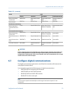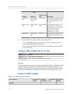
HART/RS-485 communication parameters include:
• HART Address (Polling Address)
Procedure
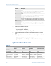
1. Set Protocol to HART RS-485.
2. Set Baud Rate to match the baud rate that will be used by your HART master.
3. Set Parity to match the parity that will be used by your HART master.
4. Set Stop Bits to match the stop bits setting that will be used by your HART master.
5. Set HART Address to a unique value on your network.
Valid address values are between 0 and 15. The default address (0) is typically used
unless you are in a multidrop environment.
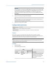
Tip
Devices using HART protocol to communicate with the transmitter may use either HART
Address or HART Tag (Software Tag) to identify the transmitter. Configure either or both, as
required by your other HART devices.
6.7.3 Configure Modbus/RS-485 communications
Display
Not available
ProLink II ProLink > Configuration > Device > Digital Comm Setting
Field Communicator Configure > Manual Setup > Inputs/Outputs > Communications > Setup RS-485 Port
Overview
Modbus/RS-485 communications parameters control Modbus communication with the
transmitter's RS-485 terminals.
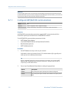
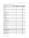
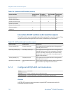
Modbus/RS-485 communications parameters include:
•
Disable Modbus ASCII
•
Protocol
• Modbus Address (Slave Address)
•
Floating-Point Byte Order
•
Additional Communications Response Delay
Important
To minimize configuration requirements, the transmitter uses an auto-detection scheme when
responding to a connection request. With this auto-detect feature, you do not need to enter some
Modbus communication parameters.
Integrate the meter with the control system
Configuration and Use Manual 117


