


Acquiring Waveforms
CSA7000 Series, TDS7000 Series, & TDS6000 Series Instruments User Manual
3-11
Coupling. All instruments and probes specify a maximum signal level. (See
Specifications in your user manuals for exact limits.) Exceeding the limit, even
momentarily, may damage the input channel. Use external attenuators, if
necessary, to prevent exceeding the limits.
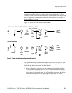
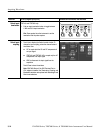
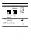
Coupling determines whether an input signal is directly connected to the input
channel, connected through a DC blocking capacitor (TDS7104 & TDS7054), or
not connected at all. These three choices are refereed to as DC coupling, AC
coupling, and GND coupling.
The input resistance of each input channel is either 50 Ω or you can select 50 Ω
or 1 MΩ, depending on the model. To properly terminate signals in other
impedance environments, use an adapter.
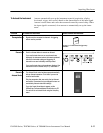
All probes expect a specific coupling and input termination. Both coupling and
input termination resistance are displayed on screen.
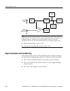
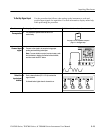
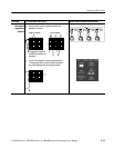
Scaling and Positioning. These key controls determine the portion of the input
signal presented to the acquisition system:
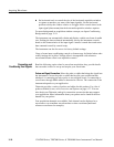
H Set vertical scaling, positioning, and DC off sets to display the featur es of
intere st on your wavef orm and avoid clipping. (See Note that follows.)
Vertic al Acquisition Window Considerations on page 3--20 desc ribe s the
vertic a l acquisition window.
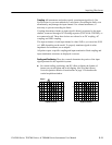
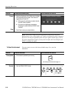
Clipped
Acquired waveform Displayed waveform