


Acquiring Waveforms
CSA7000 Series, TDS7000 Series, & TDS6000 Series Instruments User Manual
3-9
NOTE. Terminology: This manual uses the terms vertical acquisition window and
horizontal acquisition window throughout this section and elsewhere. These
terms refer to the vertical and horizontal range of the segment of the input signal
that the acquisition system acquires. The terms do not refer to any windows or
display windows on screen.
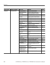
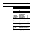
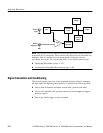
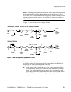
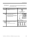
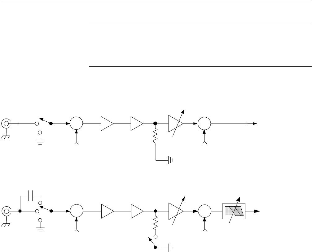
Figure 3--1 shows the model for each input channel.
+
---
+
+
Σ
Σ
Vertical
offset
Coupling
Input
termination
Vertical
scale
Vertical
position
To the
remainder
of the
acquisition
system
Bandwidth
limit
Scale = K1 * K2 * K3
External
attenuation
Probe
K1 K2 K3
50 Ω
+
---
+
+
Σ
Σ
Vertical
offset
Coupling
Input
termination
Vertical
scale
Vertical
position
To the
remainder
of the
acquisition
Bandwidth
limit
Scale = K1 * K2 * K3
External
attenuation
50 Ω
Probe
K1
K2
K3
CSA7000 Series, TDS7404, TDS7254, TDS7154, TDS6604, & TDS6404
TDS7104 & TDS7054
Figure 3- 1: Input and Acquisition Systems and Controls
Use input conditioning to ensure the instrument acquires the data that you want
to display, measure, or otherwise process. To ensure the best possible data for
displaying and further processing, do the following:
H Set the vertical scale to control the size of the vertical acquisition window
for each channel to capture part or all of the vertical amplitude of the input
signal. When vertical scaling is set to capture only a fraction of the input
signal range (for increased detail), the vertical offset control may be used to
determine which portion of the input signal is captured by the vertical
acquisition window.