


Appendix A: Specifications
A-26
CSA7000 Series, TDS7000 Series, & TDS6000 Series Instruments User Manual
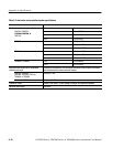
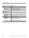
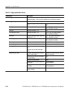
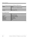
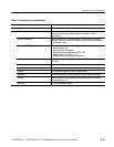
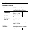
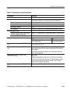
Table A- 4: Trigger specifications (Cont.)
Characteristic Description
Advanced trigger sensitivity, typical For vertical scale settings ≥10 mV/div and ≤1V/div
Advanced triggers: 1.0 div, from DC to 500 MHz at the TekConnect connector
Advanced trigger timing For vertical scale settings ≥10 mV/div and ≤1V/div
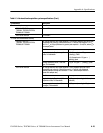
Minimum recognizable event width or
time
Minimum re-arm time to recognize next
event
Glitch type Minimum glitch width = 1 ns 2 ns + (5% of glitch width setting or
25 ns, whichever is smaller)
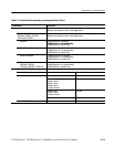
Runt type Minimum runt width = 2 ns 2ns
Time-qualified runt type Minimum runt width = 2 ns 8.5 ns + (5% of runt width setting or
25 ns, whichever is smaller)
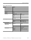
Width type Minimum difference between upper and
lower limits = 1 ns
2 ns + (5% of upper limit setting or
25 ns, whichever is smaller)
Transition type Minimum transition time = 600 ps 8.5 ns + (5% of transiti on time setting or
25 ns, whichever is smaller)
Timeout type Minimum timeout time = 1 ns 2 ns + 5% of timeout setting
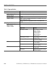
Pattern type, typical Minimum time the pattern is true = 1 ns 1ns
State type, typical Minimum true time before clock edge =
1ns
Minimum true t ime after clock edge =
1ns
1ns
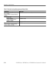
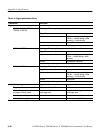
Setup/Hold type, typical Minimum clock pulse width from active
edge to inactive edge
Minimum clock pulse width from inactive
edge to active edge
2.6 ns (3 ns on TDS7104 & TDS7054) +
hold time setting
2ns
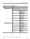
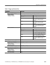
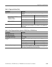
Setup and Hold parameters Limits
Setup time (time from data transition to
clock edge)
--100 ns minimum
+100 ns maximum
Hold time (time from clock edge to data
transit ion)
--1 ns minimum
+102 ns maximum
Setup time + Hold time (algebraic sum of
the two settings)
+2 ns minimum