


Creating and Using Math Waveforms
3- 216
CSA7000 Series, TDS7000 Series, & TDS6000 Series Instruments User Manual
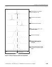
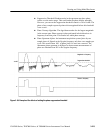
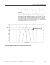
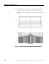
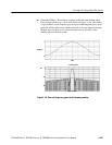
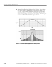
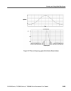
H Choice of a window. Your choice of window function will depend on the
input source characteristics which you want to observe and the characteris-
tics of the window function. The window characteristics are shown in
Table 3--13.
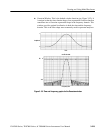
H FFT length. The FFT length is controlled so that the gate width in samples is
never more than 0.8 of the FFT length. Thus, zero fill is always in effect.
This essentially eliminates scallop loss errors in magnitude that would occur
without zero fill.
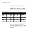
Table 3- 13: Window characteristics
Window 3dBBWinbins Scallop loss
Nearest
side lobe
Zero phase
reference
Coefficients
Rectangular
0.89 3.96 dB --13 dB 50% 1.0
Hamming
1.3 1.78 dB --43 dB 50% 0.543478, 0.456522
Hanning
1.44 1.42 dB --32 dB 50% 0.5, 0.5
Kaiser--Bessel
1.72 1.02 dB --69 dB 50% 0.40243, 0.49804, 0.09831,
0.00122
Blackman -- Harris
1.92 0.81 dB --92 dB 50% 0.35875, 0.48829, 0.14128,
0.01168
Gaussian
2.0 0.76 dB --79 dB 50% a = 3.75 (not cosine series)
Flattop2
3.8 0.0065 dB --90 dB 50% 0.213348, --0.206985,
0.139512, --0.043084,
0.003745
Tek Exponential
1.42 0.60 dB --67 dB 20% na
H 3 dB BW in B ins. This is the bandwidth of the filter response of the spectral
analyzer to a sine wave input for a given window function. It is given in
units of bins. A bin is the interval between spectral samples when the
interpolation ratio due to FFT zero fill is one. The bandwidth is measured
between the points on the lobe that are 3 dB down from the peak of the lobe.
The bandwidth in Hz may be computed by dividing the BW in bins by the
gate duration in seconds. This is also referred to as resolution
bandwidth (RBW).