


Triggering
CSA7000 Series, TDS7000 Series, & TDS6000 Series Instruments User Manual
3- 111
Overview Control elements and resourcesTo trigger on setup/hold time violations (Cont.)
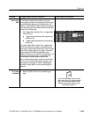
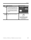
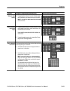
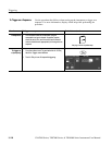
Define the data
source
3. To select the channel that is to contain the data signal,
touch Data Source, and select the source from the list.
Note. Do not select the same channel for both the data
and clock sources.
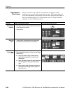
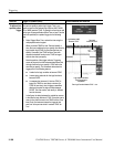
Define the clock
source and
edge
4. To select the channel that is to contain the clock signal
and the edge to use to clock, touch Clock Source, and
select the source from the list.
Do not select the same channel for both the data and
clock sources.
5. To select the edge to use to clock, select either Pos or
Neg from the Clock Edge window.
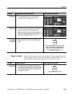
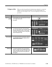
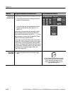
Set the data and
clock levels
To set the transition levels t hat the clock and data must cross
to be recognized by the instrument:
6. Touch Data Level and use the multipurpose knobs or
keypad to set the data level.
7. Touch Clock Level and use the multipurpose knobs or
keypad to set the clock level.
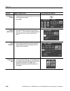
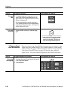
Note. You can set the levels to a value appropriat e to
either TTL or ECL logic families. To do so, touch either
the Data Level or Clock Level, and select the keypad;
touch either TTL or ECL.
The instrument uses the clock level that you set to
determine when a clock edge occurs. The instrument
uses the point the clock crosses the clock level as the
reference point from which it measures setup and hold
time settings.