


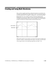


Creating and Using Math Waveforms
CSA7000 Series, TDS7000 Series, & TDS6000 Series Instruments User Manual
3- 193
Integral waveforms find use in the following applications:
H Measuring power and energy, such as in switching power supplies
H Characterizing mechanical transducers, as when integrating the output of an
accelerometer to obtain velocity
The integral math waveform, derived from the sampled waveform, is computed
based on the following equation:
y(n) = scale
n
Σ
i = 1
x(i) + x(i − 1)
2
T
Where: x (i) is the source waveform
y(n) is a point in the integral math waveform
scale is the output scale factor
T is the time between samples
Since the resultant math waveform is an integral waveform, its vertical scale is in
volt-seconds (its horizontal scale is in seconds). The source signal is integrated
over its entire record length; therefore, the math waveform record length equals
that of the source waveform.
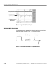
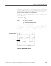
Offset and Position. When creating integrated math waveforms from live channel
waveforms, consider the following topics:
H You should scale and position the source waveform so that it is contained on
screen. (Off screen waveforms may be clipped, which will result in errors in
the integral waveform).
H You can use vertical position and vertical offset to position your source
waveform. The vertical position and vertical offset will not affect your
integral waveform unless you position the source waveform off screen so
that it is clipped.
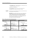
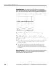
DC Offset. The source waveforms that you connect to the instrument often have
a DC offset component. The instrument integrates this offset along with the time
varying portions of your waveform. Even a few divisions of offset in the source
waveform may be enough to ensure that the integral waveform saturates (clips),
especially with long record lengths.