


Triggering
3-80
CSA7000 Series, TDS7000 Series, & TDS6000 Series Instruments User Manual
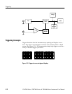
Overview Control elements and resourcesTriggering from the front panel (Cont.)
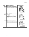
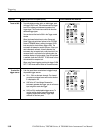
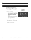
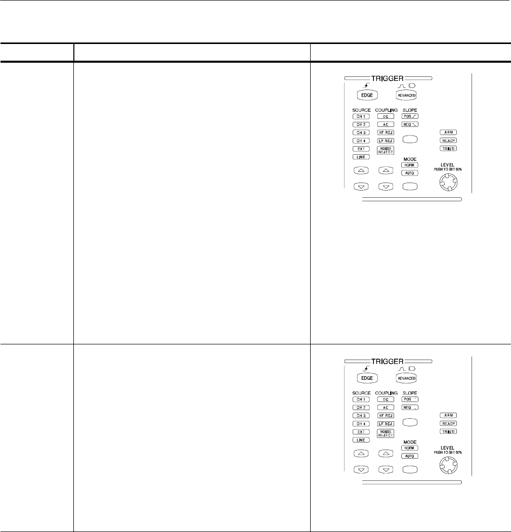
To set to 50% 5. To quickly obtain an edge, glitch, or width trigger, push
the trigger LEVEL knob. The instrument sets the trigger
level to the halfway point between the peaks of the
trigger signal. This function has no effect for the other
advanced trigger types.
You can also set the level to 50% in the Trigger control
window.
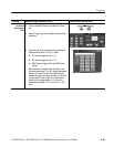
When the phased l ocked loop is active (Comm and
Serial Trigger only which are optional on the TDS7000
Series & TDS6000 Series), pushing the trigger LEVEL
knob recycles the clock-recovery trigger circuit. The
instrument will attempt to acquire lock once. If the input
data is disrupted, removed, or heavily distorted, the
instrument may not acquire lock or may lose lock. If the
recovered clock is not locked to the incoming data, the
waveform display will not be stable. Once the input data
is available, press the PUSH SET TO 50% knob to force
the instrument to reacquire lock.
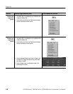
When using Comm triggering, pushing the trigger PUSH
SET TO 50% knob sets the levels for t he selected code.
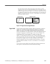
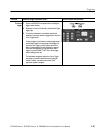
To sel ect the
trigger source
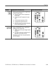
6. Push the up and down arrow buttons to toggle through
the possible trigger sources:
H CH 1 - CH 4 are the input channels. The channel
you select as a trigger source will function whether
it is displayed or not.
H LINE is the AC Line Voltage. Because the
instrument generates the trigger, you do not have to
input a si gnal to create the trigger.
H AUX is a fifth, nondisplayable trigger source. To
use the auxiliary trigger, connect the external
triggering signal to the Auxiliary Trigger input
connector on the front panel.