


Triggering
CSA7000 Series, TDS7000 Series, & TDS6000 Series Instruments User Manual
3-91
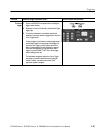
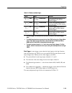
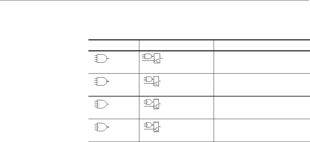
Table 3- 5: Pattern and state logic
Pattern State Definition
1, 2
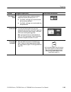
AND Clocked AND If all the preconditions selected for the
logic inputs
3
are TRUE, then the
instrument triggers.
NAND Clocked NAND If not all of the preconditions selected
for the logic inputs
3
are TRUE, then the
instrument triggers.
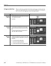
OR Clocked OR If any of the preconditions selected for
the logic inputs
3
are TRUE, then the
instrument triggers.
NOR Clocked NOR If none of the preconditions selected for
the logic inputs
3
are TRUE, then the
instrument triggers.
1
For state triggers, the definition must be met at the time the clock input changes
state.
2
The definitions given here are correct for the Goes TRUE setting in the Trigger When
menu. If that menu is set to Goes False, swap the definition for AND with that for
NAND and for OR with NOR for both pattern and state types.
3
The logic inputs are channels 1, 2, 3, and 4 when using Pattern triggers. For State
triggers, channel 4 becomes the clock input, leaving the remai ning channels as logic
inputs.
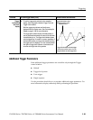
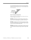
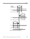
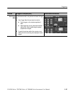
State Trigger. A state trigger occurs when the logic inputs to the logic function
cause the function to be TRUE (or at your option FALSE) at the time the clock
input changes state. When you use a state trigger, you define:
H The precondition for each logic input, channels 1, 2, and 3
H The direction of the state change for the clock input, channel 4
H The Boolean logic function — select from clocked AND, NAND, OR, and
NOR
H The condition for triggering — whether the trigger occurs when the Boolean
function becomes TRUE (logic high) or FALSE (logic low)
The state (and pattern) logic choices are summarized in Table 3--5.