


Acquiring Waveforms
CSA7000 Series, TDS7000 Series, & TDS6000 Series Instruments User Manual
3-63
O/E Converter
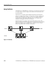
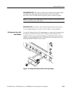
CSA7000 Series: The O/E converter converts the optical signal to an electrical
signal for use in the instrument. Figure 3--18 on page 3--64 shows the input and
output connectors.
This section describes the front panel, connecting to the circuit under test, how to
select the optical wavelength, and explains optical bandwidth.
CAUTION. To avoid damaging your instrument, replace the protective cap on the
input connector when the Optical Input is not in use.
To prevent loss of optical power or damage to the optical connectors, keep the
connectors clean at all times. Also insure that all connectors and jumpers
attached to the inputs are clean prior to insertion. See Cleaning Optical
Connectors on page 3--66.
Take care to preserve the integrity of optical connectors by keeping them free of
contamination. For cleaning information, see Cleaning Optical Connectors on
page 3--66.
The instrument can couple to multimode fibers with a core diameter of
62.5/50 m or singlemode fiber with a core diameter of 9 m. Alternate types
can be coupled by use of UCI (universal connector interface) series adapters.
(Refer to a current Tektronix catalog for details.)
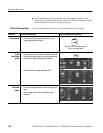
Attach the fiber optic cable with a suitable connector or a UCI Interface adapter
to the optical input receptacle as follows:
1. Firmly press the cable connector or adapter over the interface ferrule until it
reaches the stop.
2. Rotate the cable connector or the adapter body until the antirotation pin
engages.
3. Firmly tighten the cable connector or the adapter shell. Tighten with finger
pressure only.
4. To remove, unscrew the cable connector or adapter shell.
Connecting Optical
Signals