


Glossary
CSA7000 Series, TDS7000 Series, & TDS6000 Series Instruments User Manual
Glossary- 3
Control knob
See Knob.
Channel
One type of input used for signal acquisition. The instrument has four
channels.
Channel/probe deskew
A relative time delay for each channel. This lets you align signals to
compensate for the fact that signals may come in from cables of differing
length.
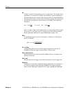
Channel Reference Indicator
The indicator on the left side of the display that points to the position ar ound
which the waveform contra c ts or expa nds when ver tica l scale is cha nged. This
position is ground when of f set is set to 0 V; other wise, it is ground plus of f set.
Control window
A group of related controls for a major instrument function that the
instrument displays at the right of the screen.
Coupling
The association of two or more circuits or systems in such a way that power
or information can be transferred from one to the other. You can couple the
input signal to the trigger and vertical systems several different ways.
Cursors
Paired markers that you can use to make measurements between two waveform
locations. The instrument displays the values (expre sse d in volts or time) of the
position of the active cursor and the distance betwee n the two cursor s.
Cycle area
A measurement of waveform area taken over one cycle. Expressed in
volt-seconds. Area above ground is positive; area below ground is negative.
Cycle mean
An amplitude (voltage) measurement of the arithmetic mean over one cycle.
Cycle RMS
The true Root Mean Square voltage over one cycle.