


Measuring Waveforms
CSA7000 Series, TDS7000 Series, & TDS6000 Series Instruments User Manual
3- 163
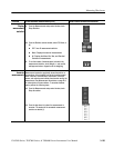
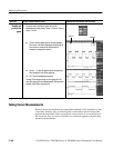
After you have selected the source from the Cursors Setup control window, you
can operate the cursor from the front-panel knobs and buttons.
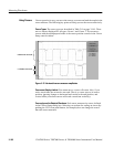
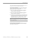
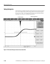
Cursors Treat Sources Independently. Each cursor can take a different, indepen-
dent source, with each source having its own amplitude scale. Consider the
example presented by Figure 3--37 on page 3--162:
H Cursor 1 is set to measure channel 3 (Ch3), which is set to 100 mV per
division, so cursor readout v1 measures Ch3 relative to its ground as
3 divisions x 100 mV/div, or about 300 mV.
H Cursor 2 is set to measure reference 4 (Ref4), which is set to 20 mV per
division, so cursor readout v2 measures R4 relative to its ground as
3 divisions x 20 mV/div, or about 60 mV.
H Note that the value of each graticule division is not readily apparent relative
to the delta readout, because the delta-amplitude readout (∆v) must account
for the different amplitude-scale settings of the sources. To do so, the ∆v
readout displays the results of v2 -- v1 (60 mV -- 300 mV = --240 mV),
automatically accounting for the different scales of the cursor sources.
NOTE. If a cursor readout does not seem correct, check the source of each cursor
in the Cursor setup dialog box. Each cursor readout relates to the amplitude and
time base settings of its source.
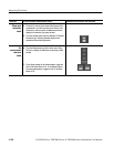
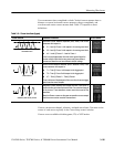
Vertical Cursors Measure from the Trigger Point. Remember that each vertical
cursor measures the time from the trigger point to itself. This relationship is
shown in Figure 3--38 on page 3-- 164.