


Acquiring Waveforms
3-64
CSA7000 Series, TDS7000 Series, & TDS6000 Series Instruments User Manual
To keep the optical input power to an appropriate level, it may be necessary to
attenuate the optical signal.
CAUTION. To avoid damaging the optical input, to maintain the levels within
performance range, and to avoid clipping; attenuate optical signals to less than
that listed in Absolute maximum nondestructive optical input on page A--34 and
Maximum nonsaturating linear response to transient input on page A--34.
Front Panel Connectors
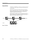
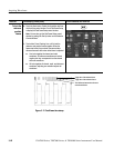
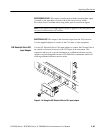
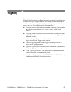
CSA7000 Series: The O/E converter connectors are shown in Figure 3--18.
OPTICAL IN
(UCI optical input
connector)
ELECTRICAL
OUT
RECOVERED
DATA
RECOVERED
CLOCK
Figure 3- 18: Optical-to-Electrical converter and recovered clock and data
connectors
The optical input connector uses a universal connector interface (UCI) that
allows use of many standard fiber-optic female connector styles. Some of the
standard UCI interfaces supported are FC, ST, SC, and DIN. (Refer to a current
Tektronix catalog for details.)
Clock and data-recovery circuitry provides recovered clock and data outputs. The
signals are also available internally for use by the instrument. Circuitry also
provides electrical output from the O/E (optical to electrical) converter.
RECOVERED DATA. This output provides a 50 Ω, AC -coupled, ~ECL/2 level
signal from the optical data signal. This signal is digitally buffered and retimed
to be synchronous with the serial recovered clock.
Attenuating Optical
Signals
Optical Input Connector
Output Connectors