


Measuring Waveforms
3- 182
CSA7000 Series, TDS7000 Series, & TDS6000 Series Instruments User Manual
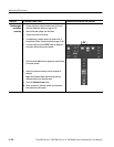
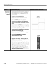
Overview Related control elements and resourcesTo deskew channels (Cont.)
Compensate
probe timing
(deskew)
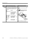
2. Connect fixture to the instrument (see To Connect the
Probe Calibration Fixture on page 3--173). CSA7000
Series, TDS7000 Series, and TDS6404: The jumper
must be installed.
3. Connect up to four probes to the fixture.
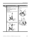
4. Display all the channels that you want to deskew.
5. Push the AUTOSET button on the instrument.
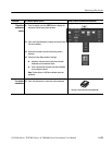
6. Adjust the Vertical SCALE and POSITION for each
channel so that the signals overlap and are centered on
screen.
7. Adjust the horizontal POSITION, as indicated by the red
pointer at the top of the graticule area, to the center of
the display. The red pointer is the trigger position and all
channels will be aligned to this point.
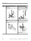
8. Adjust the horizontal SCALE so that the differences i n
the channel delays are clearly visible.
9. From the toolbar, touch the VERT button to display the
Vertical setup control window.
10. Touch the Probe Deskew button to display the
channel-deskew control window.
11. Select one of the channels. The channel that is the
trigger source will already be at the trigger position and
should not need to be deskewed.
Note. Do the next step at a signal amplitude within the
same attenuator range (vertical scale) as your planned
signal measurements. Any change to the vertical scale
after deskew is complete may introduce a new
attenuation level (you can generally hear attenuator
settings change) and, therefore, a slightly different
signal path. This different path may cause a variation i n
timing accuracy between channels.