


Appendix A: Specifications
A-32
CSA7000 Series, TDS7000 Series, & TDS6000 Series Instruments User Manual
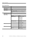
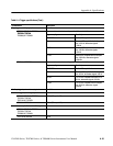
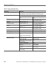
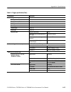
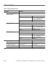
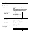
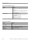
Table A- 6: Input/output port specifications (Cont.)
Characteristic Description
n Probe Compensator Output Front-panel BNC connector, requires Probe Cal Deskew Fixture for probe
attachment
Note: During probe calibration only, a relay switches a DC calibration voltage
to this output in place of the 1 kHz square wave. This voltage varies from
--10 V to +10 V with a source impedance less than 1 W and short circuit
current as high as 300 mA.
CSA7404, CSA7154,
T
D
S
7
4
0
4
T
D
S
7
2
5
4
T
D
S
7
1
5
4
Output voltage Frequency
T
D
S
7
4
0
4
,
T
D
S
7
2
5
4
,
T
D
S
7
1
5
4
,
TDS6604, & TDS6404
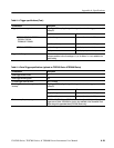
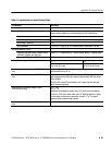
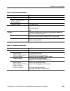
200 mV (from base to top) ± 20% into a 50 Ω
load (Vol = 0.8 V, Voh = 1 V typical)
1 kHz ± 5%
400 mV (from base to top) ± 20% into a ≥
10 kΩ load (Vol = 1.6 V, Voh = 2 V typical)
TDS7104 & TDS7054 1.0 V (from base to top) ± 1.0% into a ≥ 50 Ω
load
1 kHz ± 5%
n Analog Signal Output amplitude
CSA7404, CSA7154,
TDS7404, TDS7254, TDS7154,
TDS6604, & TDS6404
BNC connector, provides a buff ered version of the signal that is attached to
the channel 3 input when channel 3 is the trigger source
20 mV/div ± 20%intoa1MΩ l oad
10 mV/div ± 20% into a 50 Ω load
Offset: between --100 mV and --170 mV into 50 Ω
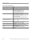
TDS7104 & TDS7054 Front-panel BNC connector, provides a buffered version of the signal that i s
attached to the channel 3 input
20 mV/div ± 20%intoa1MΩ l oad
10 mV/div ± 20% into a 50 Ω load
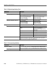
Analog Signal Output bandwidth, typical ,
TDS7104 & TDS7054
100 MHz into a 50 Ω load
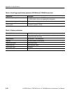
n Auxiliary Output levels BNC connector, provides a TTL-compatible pulse (polarity selectable) for
each A or B trigger (selectable)
V
out
high V
out
low (true)
≥2.5 V into open circuit,
≥1.0 V into 50 Ω load
≤0.7 V with ≤4masink,
≤0.25 V into 50 Ω load