


Incoming Inspection
CSA7000 Series, TDS7000 Series, & TDS6000 Series Instruments User Manual
1-31
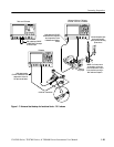
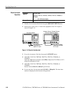
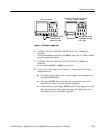
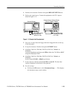
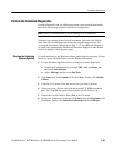
CSA7404, CSA7154, TDS7404, TDS7254,
TDS7154, TDS6604, & TDS6404
BNC cable from PROBE
COMPENSATION output
to CH 1 input
TDS7104 & TDS7054
BNC cable from PROBE
COMPENSATION
output to CH 1 input
Figure 1- 10: Setup for trigger test
4. CSA7404, CSA7154, TDS7404, TDS7254, TDS7154, TDS6604, &
TDS6404:
Touch the Vert button and then touch Offset. Adjust the Ch1 Offset to 0.8 V
using the multipurpose knob.
5. CSA7404, CSA7154, TDS7404, TDS7254, TDS7154, TDS6604, &
TDS6404:
Set the Vertical SCALE to 100 mV per division.
6. Verify that the main trigger system operates: Confirm that the following
statements are true.
H The trigger level readout for the A (main) trigger system changes with
the trigger-LEVEL knob.
H The trigger-LEVEL knob can trigger and untrigger the square-wave
signal as you rotate it. (Leave the signal untriggered).
H Pushing the front-panel trigger LEVEL knob sets the trigger level to the
50% amplitude point of the signal and triggers the signal that you just
left untriggered. (Leave the signal triggered.)