


3 - 8
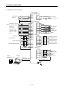
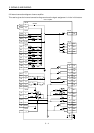
3. SIGNALS AND WIRING
Device name
Devices
symbol
Connector
pin No.
Functions/Applications
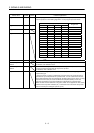
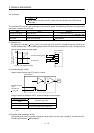
Select the program number from among those combined by DI0, DI1, DI2 and DI3
to start operation on the leading edge of ST1 in the program operation mode.
Program No. selection 1 DI0 CN1B-5
Input signal (Note)
DI3DI2DI1DI0
Program No.
Program No. selection 2 DI1 CN1B-14
0000 1
0001 2Program No. selection 3 DI2
0010 3
0011 4
0100 5
0101 6
0110 7
0111 8
1000 9
1001 10
1010 11
1011 12
1100 13
1101 14
1110 15
1111 16
Program No. selection 4 DI3
Note. 0: OFF
1: ON
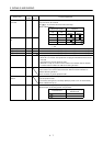
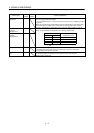
Override selection OVR Turn OVR on to make override (VC) valid.
External torque limit
selection
TL Turn TL on to make analog torque limit (TLA) valid.
For details, refer to Section 3.4.4.
Internal torque limit
selection
TL2 Turn TL2 off to make parameter No.28 (Internal torque limit 1) valid, or turn it on
to make parameter No.29 (Internal torque limit 2) valid.
For detailes, refer to Section 3.4.4.
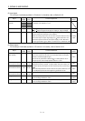
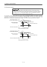
Proportion control PC Turn PC on to bring the speed amplifier from the proportional integral type to the
proportional type.
If the servo motor at a stop is rotated even one pulse due to any external factor, it
generates torque to compensate for a position shift. In such a case where the axis
will be locked mechanically after Movement complete (PED) has turned off, turning
Proportion control (PC) on as soon as Movement complete (PED) turns off can
suppress unnecessary torque that attempts to compensate for a position shift.
When the shaft is to be locked for a long time, switch on the proportion control (PC)
and External torque limit selection (TL) at the same time to make the torque less
than the rated by the analog torque limit (TLA).