


1 - 8
1. FUNCTIONS AND CONFIGURATION
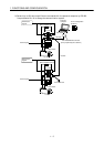
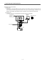
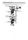
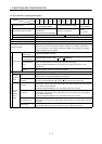
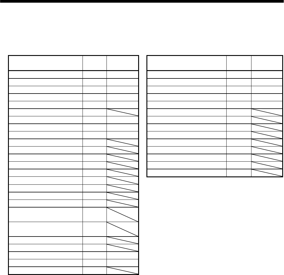
1.1.3 I/O devices
This servo amplifier allows devices to be allocated to the pins of connector CN1A/CN1B as desired. The
following devices can be allocated. For device details, refer to Section 3.3.2.
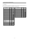
Input device Symbol
Factory-
allocated pin
Output device Symbol
Factory-
allocated pin
Servo-on SON CN1A-19 Trouble ALM CN1B-18
Reset RES CN1B-15 Ready RD CN1B-19
Forward rotation stroke end LSP CN1B-16 Movement complete PED CN1B-6
Reverse rotation stroke end LSN CN1B-17 Zeroing completion ZP CN1A-18
Forward rotation start ST1 CN1B-7 Program output 1 OUT1 CN1B-4
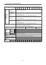
Reverse rotation start ST2 Program output 2 OUT2
Proximity dog DOG CN1A-8 Program output 3 OUT3
Program No. selection 1 DI0 CN1B-5 Electromagnetic brake interlock MBR
Program No. selection 2 DI1 CN1B-14 Position range POT
Program No. selection 3 DI2 Warning WNG
Program No. selection 4 DI3 Battery warning BWNG
Forced stop EMG Limiting torque TLC
Automatic/manual selection MD0 Temporary stop PUS
Override selection OVR SYNC synchronous output SOUT
External torque limit selection TL
Internal torque limit selection TL2
Proportion control PC
Temporary stop/restart STP
Manual pulse generator
multiplication 1
TP0
Manual pulse generator
multiplication 2
TP1
Gain switch CDP
Current position latch input LPS
Program input 1 PI1 CN1B-8
Program input 2 PI2 CN1B-9
Program input 3 PI3