


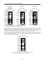
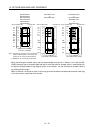
14 - 26
14. OPTIONS AND AUXILIARY EQUIPMENT
14.1.7 External digital display (MR-DP60)
When using the MR-DP60, set "
1 4" in parameter No. 16.
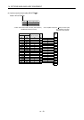
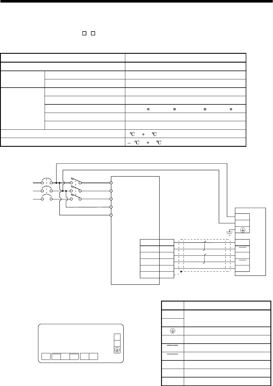
(1) Specifications
Item Specifications
Display Red seven-segment LED, signed, six digits
Permissible voltage fluctuation Single phase, 85 to 253VAC, 50/60HzPower supply
Current consumption Within 200mA
Interface Conforms to RS-422A.
Baudrate 4800bps, asynchronous
Bit length Start bit 1, date bit 8, parity bit 1, stop bit 1
Protocol MELSERVO protocol
Communication
Communication commands Commands dedicated to MELSERVO
Operating temperature / humidity range 0 to 60 , 90%RH or less, non-condensing
Storage temperature range 5 to 70
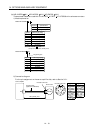
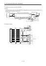
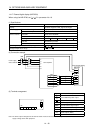
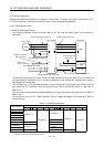
(2) Connection example
Power supply
200 to 230VAC
Servo amplifier
NFB
RDN
SDP
SDN
P24M
SD
RDP
5
15
9
19
1
CN3
Plate
External digital display
MR-DP60
L
1
L
2
TXD
TXD
RXD
LG
RXD
L
1
L
2
L
3
L
11
L
21
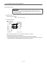
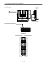
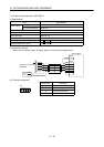
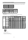
(3) Terminal arrangement
Signal Description
L
1
L
2
100 to 230VAC power input
Ground
RXD Receive signal input
RXD Inverse receive signal input
TXD Inverse transmission signal output
TXD Transmission signal output
P5 5VDC output
(Note)
TB2
L
1
L
2
TXD TXDRXDRXD P5 LG
TB1
LG Control common
Note: The 5VDC output is designed for the internal control circuit and used to make a voltage check, etc. Do not use this terminal to
supply a voltage to the other equipment.