


15 - 23
15. COMMUNICATION FUNCTIONS
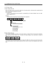
(5) Read of the statuses of output devices
Read the ON/OFF statuses of the output devices.
(a) Transmission
Transmit command [1][2] and data No. [8][0].
Command Data No.
[1][2] [8][0]
(b) Reply
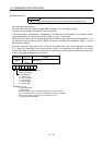
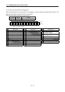
The slave station sends back the statuses of the output devices.
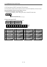
b31
b0
0:OFF
1:ON
b1
Command of each bit is transmitted to the master
station as hexadecimal data.
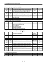
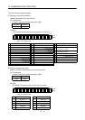
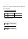
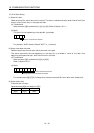
bit Signal name bit Signal name bit Signal name
0 Ready (RD) 10 Electromagnetic brake (MBR) 19 Temporary stop (PUS)
1 11 Dynamic brake interlock (DBR) 20 Program output 1 (OUT1)
2 12 21 Program output 2 (OUT2)
3 Limiting torque (TLC) 13 22 Program output 3 (OUT3)
4 14 23 SYNC Synchronous output (SOUT)
5 15 Battery warning (BWNG) 24 Movement complete (PED)
61625
7Warning (WNG) 26
8Trouble (ALM)
17
Home position return completion
(ZP)
27
9 18 Position range (POT) 28
15.12.5 Device ON/OFF
POINT
The ON/OFF states of all devices in the servo amplifier are the states of
the data received last. Hence, when there is a device which must be kept
ON, send data which turns that device ON every time.
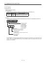
Each input device can be switched on/off. However, when the device to be switched off exists in the
external input signal, also switch off that input signal.
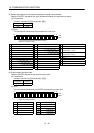
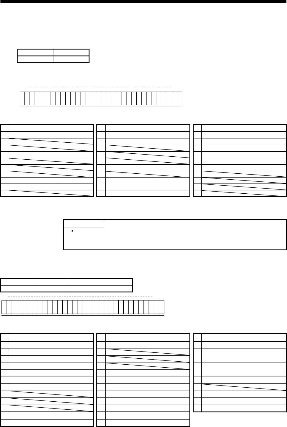
Send command [9][2], data No. [6][0] and data.
Command Data No. Set data
[9][2] [6][0] See below.
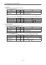
b31 b0
0:OFF
1:ON
b1
Command of each bit is transmitted to the slave
station as hexadecimal data.
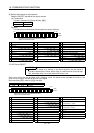
bit Signal name bit Signal name bit Signal name
0 Servo-on (SON) 12 Reverse rotation start (ST2) 24 Temporary stop/restart (STP)
1 Forward rotation stroke limit (LSP) 13
2 Reverse rotation stroke limit (LSN) 14
25
Manual pulse generator
multiplication 1 (TP0)
3 External torque limit selection (TL) 15
4 Internal torque limit selection (TL2) 16 Forced stop (EMG)
26
Manual pulse generator
multiplication 2 (TP1)
5 Proportion control selection (PC) 17 Automatic/manual selection (MD0) 27 Gain switch (CDP)
6 Reset (RES) 18 Proximity dog (DOG) 28
7 19 Program No. selection 1 (DI0) 29 Program input 1 (PI1)
8 20 Program No. selection 2 (DI1) 30 Program input 2 (PI2)
9 21 Program No. selection 3 (DI2) 31 Program input 3 (PI3)
10 Current position latch input (LPS) 22 Program No. selection 4 (DI3)
11 Forward rotation start (ST1) 23 Override selection (OVR)