


13 - 2
13. CHARACTERISTICS
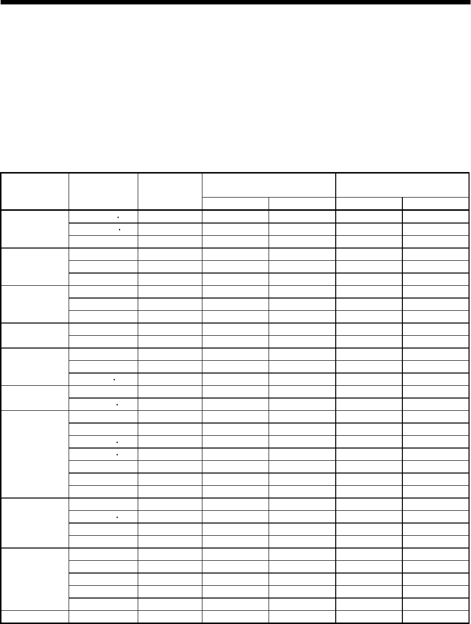
13.2 Power supply equipment capacity and generated loss
(1) Amount of heat generated by the servo amplifier
Table 12.1 indicates servo amplifiers' power supply capacities and losses generated under rated load.
For thermal design of an enclosure, use the values in Table 13.1 in consideration for the worst
operating conditions. The actual amount of generated heat will be intermediate between values at
rated torque and servo-off according to the duty used during operation. When the servo motor is run at
less than the maximum speed, the power supply capacity will be smaller than the value in the table,
but the servo amplifier's generated heat will not change.
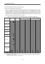
Table 13.1 Power supply capacity and generated heat per servo amplifier at rated output
(Note 2)
Servo amplifier-generated heat [W]
Area required for heat dissipation
Servo amplifier Servo motor
(Note 1)
Power supply
capacity [kVA]
At rated torque At servo-off [m
2
] [ft
2
]
HC-KFS053 13 0.3 25 15 0.5 5.4
HC-MFS053 13 0.3 25 15 0.5 5.4
MR-J2S-10CL (1)
HC-UFS13 0.3 25 15 0.5 5.4
HC-KFS23 0.5 25 15 0.5 5.4
HC-MFS23 0.5 25 15 0.5 5.4MR-J2S-20CL (1)
HC-UFS23 0.5 25 15 0.5 5.4
HC-KFS43 0.9 35 15 0.7 7.5
HC-MFS43 0.9 35 15 0.7 7.5MR-J2S-40CL (1)
HC-UFS43 0.9 35 15 0.7 7.5
HC-SFS52 1.0 40 15 0.8 8.6
MR-J2S-60CL
HC-SFS53 1.0 40 15 0.8 8.6
HC-KFS73 1.3 50 15 1.0 10.8
HC-MFS73 1.3 50 15 1.0 10.8MR-J2S-70CL
HC-UFS72
73 1.3 50 15 1.0 10.8
HC-SFS81 1.5 50 15 1.0 10.8
MR-J2S-100CL
HC-SFS102
103 1.7 50 15 1.0 10.8
HC-SFS121 2.1 90 20 1.8 19.4
HC-SFS201 3.5 90 20 1.8 19.4
HC-SFS152 153 2.5 90 20 1.8 19.4
HC-SFS202 203 3.5 90 20 1.8 19.4
HC-RFS103 1.7 50 15 1.0 10.8
HC-RFS153 2.5 90 20 1.8 19.4
MR-J2S-200CL
HC-UFS152 2.5 90 20 1.8 19.4
HC-SFS301 4.8 120 20 2.7 29.1
HC-SFS352 353 5.5 130 20 2.7 29.1
HC-RFS203 3.5 90 20 1.8 19.4
MR-J2S-350CL
HC-UFS202 3.5 90 20 1.8 19.4
HC-SFS502 7.5 195 25 3.9 42.0
HC-RFS353 5.5 135 25 2.7 29.1
HC-RFS503 7.5 195 25 3.9 42.0
HC-UFS352 5.5 195 25 3.9 42.0
MR-J2S-500CL
HC-UFS502 7.5 195 25 3.9 42.0
MR-J2S-700CL HC-SFS702 10.0 300 25 6.0 64.6
Note: 1. Note that the power supply capacity will vary according to the power supply impedance. This value assumes that the power
factor improving reactor is not used.
2. Heat generated during regeneration is not included in the servo amplifier-generated heat. To calculate heat generated by the
regenerative brake option, use Equation 14.1 in Section 14.1.1.