


84 Micro Motion
®
Model 2400S Transmitters for DeviceNet
™
Pressure Compensation and Temperature Compensation
9.2.2 Pressure correction factors
When configuring pressure compensation, you must provide the flow calibration pressure – the
pressure at which the flowmeter was calibrated (which therefore defines the pressure at which there
will be no effect on the calibration factor). Enter
20 PSI unless the calibration document for your
sensor indicates a different calibration pressure.
Two additional pressure correction factors may be configured: one for flow and one for density. These
are defined as follows:
• Flow factor – the percent change in the flow rate per psi
• Density factor – the change in fluid density, in g/cm
3
/psi
Not all sensors or applications require pressure correction factors. For the pressure correction values
to be used, obtain the pressure effect values from the product data sheet for your sensor, then reverse
the signs (e.g., if the pressure effect is
0.000004, enter a pressure correction factor of –0.000004).
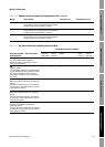
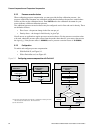
9.2.3 Configuration
To enable and configure pressure compensation:
• With ProLink II, see Figure 9-1.
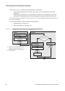
• With a DeviceNet tool, see Figure 9-2.
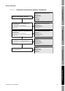
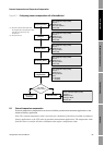
Figure 9-1 Configuring pressure compensation with ProLink II
Enter Flow factor
Configure
Enter Density factor
Enter Cal pressure
Set up output
assembly
(2)
Enter External
Pressure
Enable External Pressure
Compensation
Enable
Apply
Enter Pressure units
Set measurement unit
(1)
Yes
Done
Apply
View >
Preferences
ProLink >
Configuration >
Pressure
ProLink >
Configuration >
Pressure
Apply
Apply
Use static
pressure value?
No
(1) Pressure measurement unit must be configured to match pressure
unit used by external device. See Section 6.3.
(2) See Section 9.4.