


Configuration and Use Manual 65
Optional Configuration
Required Configuration Optional ConfigurationUsing the TransmitterUsing a DeviceNet Tool Required Configuration Optional ConfigurationUsing the TransmitterUsing a DeviceNet Tool Required Configuration Optional ConfigurationUsing the TransmitterUsing a DeviceNet Tool Required Configuration Optional ConfigurationUsing the TransmitterUsing a DeviceNet Tool
If the transmitter detects slug flow:
• A slug flow alarm is posted immediately.
• During the slug duration period, the transmitter holds the mass flow rate at the last measured
pre-slug value, independent of the mass flow rate measured by the sensor. The reported mass
flow value is set to this value, and all internal calculations that include mass flow rate will use
this value.
• If slugs are still present after the slug duration period expires, the transmitter forces the mass
flow rate to
0, independent of the mass flow rate measured by the sensor. Mass flow rate is
reported as
0 and all internal calculations that include mass flow rate will use 0.
• When process density returns to a value within the slug flow limits, the slug flow alarm is
cleared and the mass flow rate reverts to the actual measured value.
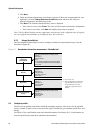
To configure slug flow parameters:
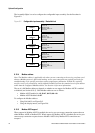
• Using ProLink II, use the Density panel in the Configuration window. See Figure B-2.
• Using a DeviceNet tool, set Attributes 3, 4, and 5 in the Diagnostics Object (0x66), Instance 1.
See Table C-7.
Note: This functionality is not available via the display menus.
Note: The slug flow limits must be entered in g/cm
3
, even if another unit has been configured for
density. Slug flow duration is entered in seconds.
Note: Raising the low slug flow limit or lowering the high slug flow limit will increase the possibility
of slug flow conditions. Conversely, lowering the low slug flow limit or raising the high slug flow limit
will decrease the possibility of slug flow conditions.
Note: If slug flow duration is set to 0, the mass flow rate will be forced to 0 as soon as slug flow is
detected.
8.8 Configuring status alarm severity
The Model 2400S transmitter can report faults in the following ways:
• Setting the “alarm active” status bit
• Writing an “alarm active” record to alarm history
• Implementing the digital communications fault action (see Section 8.10.7)
Status alarm severity determines which methods the transmitter will use when a specific alarm
condition occurs, as described in Table 8-7. (See Section 7.6 for a more detailed discussion.)
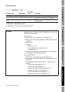
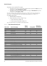
Table 8-7 Alarm severity levels and fault reporting
Severity level
Transmitter action if condition occurs
“Alarm active”
status bit set?
“Alarm active” record
written to history?
Digital communications
fault action activated?
(1)
(1) For some alarms, the digital communications fault action will not begin until the fault timeout has expired. To configure fault timeout,
see Section 8.10.8. Other fault reporting methods occur as soon as the fault condition is recognized. Table 8-8 includes information
on which alarms are affected by the fault timeout
Fault Yes Yes Yes
Informational Yes Yes No
Ignore Yes No No