


Configuration and Use Manual 127
Troubleshooting
Measurement Performance DefaultsTroubleshootingCompensation
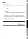
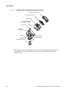
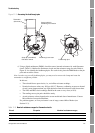
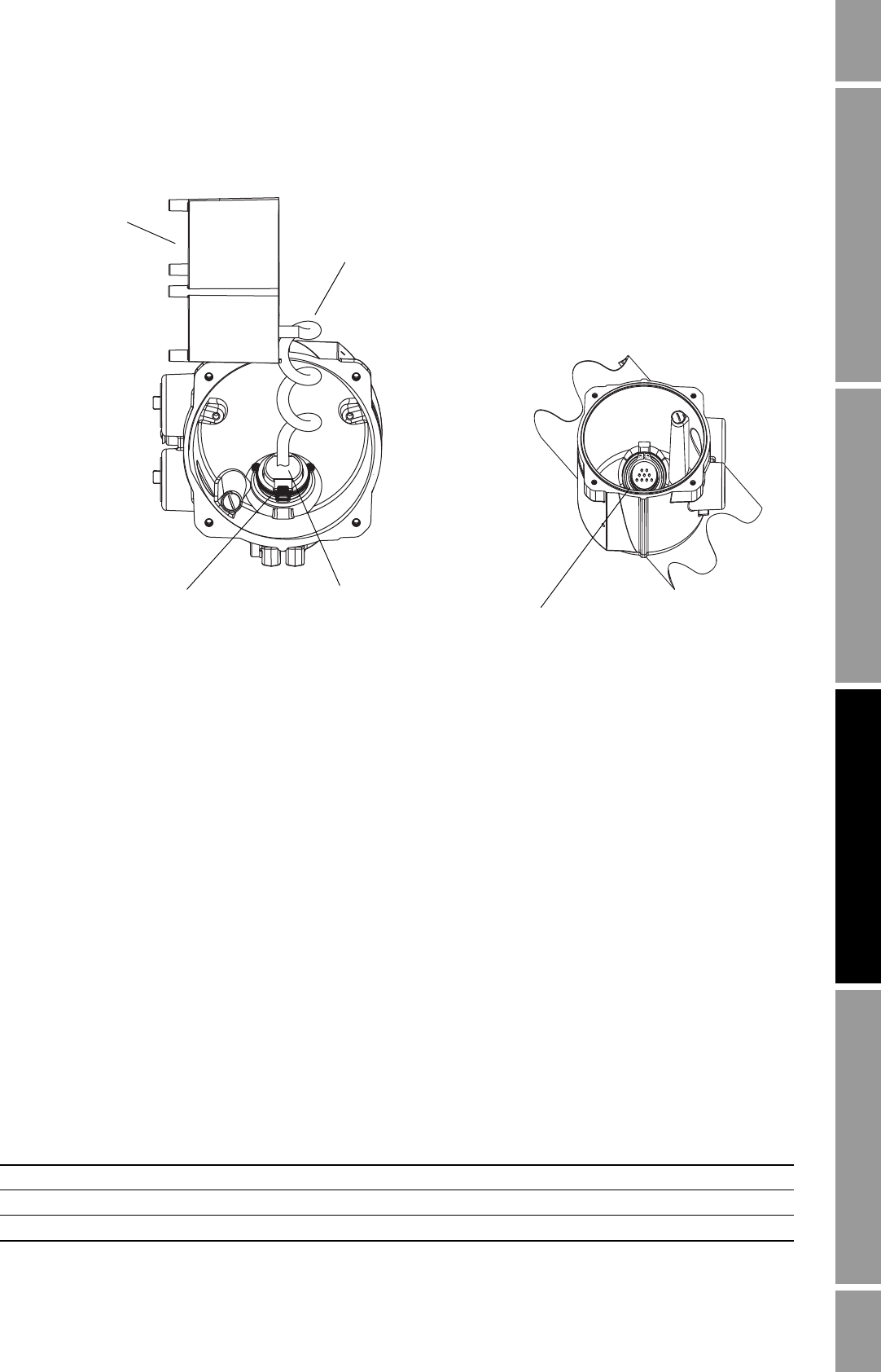
Figure 11-3 Accessing the feedthrough pins
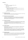
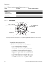
6. Using a digital multimeter (DMM), check the sensor internal resistances for each flowmeter
circuit. Table 11-8 defines the flowmeter circuits and the resistance range for each. Refer to
Figure 11-4 to identify the feedthrough pins. For each circuit, place the DMM leads on the pin
pairs and record the values.
Note: In order to access all feedthrough pins, you may need to remove the clamp and rotate the
transmitter to a different position.
In this test:
• There should be no open circuits, i.e., no infinite resistance readings.
• Nominal resistance values vary 40% per 100 °C. However, confirming an open or shorted
circuit is more important than any slight deviation from the resistance values shown here.
• The LPO and RPO circuit readings should be the same or very close (± 10%).
• The readings across pin pairs should be steady.
• Actual resistance values depend on the sensor model and date of manufacture. Contact
Micro Motion for more detailed data.
If a problem appears, or if any resistance is out of range, contact Micro Motion (see
Section 11.3).
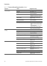
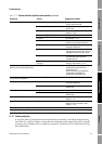
Table 11-8 Nominal resistance ranges for flowmeter circuits
Circuit Pin pairs Nominal resistance range
(1)
Drive Drive + and – 8–1500 Ω
Left pickoff Left pickoff + and – 16–1000 Ω
Right pickoff Right pickoff + and – 16–1000 Ω
Transmitter
(side view)
Sensor cable for
feedthrough connection
Feedthrough connector
Snap clip (assembled)
Pull tab to remove
Feedthrough pins