


Configuration and Use Manual 125
Troubleshooting
Measurement Performance DefaultsTroubleshootingCompensation
11.20 Checking sensor circuitry
Problems with sensor circuitry can cause several alarms, including sensor failure and a variety of
out-of-range conditions. Testing involves:
• Inspecting the cable that connects the transmitter to the sensor
• Measuring the resistances of the sensor's pin pairs and RTDs
• Ensuring that the circuits are not shorted to each other or to the sensor case
Note: To check the sensor circuitry, you must remove the transmitter from the sensor. Before
performing this test, ensure that all other applicable diagnostics have been performed. Diagnostic
capabilities of the Model 2400S transmitter have been greatly enhanced, and may provide more useful
information than these tests.
1. Follow appropriate procedures to ensure that the process of checking the sensor circuitry does
not interfere with existing measurement and control loops.
2. Disconnect the DeviceNet cable from the DeviceNet connector on the Model 2400S DN
transmitter.
3. If the transmitter is in a hazardous environment, wait five minutes.
4. Check the sensor cable and sensor connection:
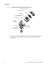
a. Referring to Figure 11-2, loosen the four captive transmitter housing cover screws and
remove the transmitter housing cover.
b. Loosen the two captive user interface screws.
c. Gently lift the user interface module, disengaging it from the connector on the transmitter.
d. Two captive screws (2.5 mm hex head) hold the transmitter in the housing. Loosen the
screws and gently lift the transmitter away from the housing. Allow the transmitter to hang
by the cable.
e. Check the cable for any signs of damage.
f. Ensure that the cable is fully plugged in and making a good connection. If it is not, reseat
the cable, reassemble the transmitter and sensor, and check operation.