


60 Micro Motion
®
Model 2400S Transmitters for DeviceNet
™
Optional Configuration
To configure damping values:
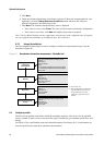
• Using ProLink II, see Figure B-2.
• Using a DeviceNet tool, see Tables C-1, C-3, and C-4.
Note: This functionality is not available via the display menus.
8.4.1 Damping and volume measurement
When configuring damping values, note the following:
• Liquid volume flow is derived from mass and density measurements; therefore, any damping
applied to mass flow and density will affect liquid volume measurement.
• Gas standard volume flow is derived from mass flow measurement, but not from density
measurement. Therefore, only damping applied to mass flow will affect gas standard volume
measurement.
Be sure to set damping values accordingly.
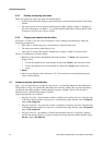
8.5 Configuring the flow direction parameter
The flow direction parameter controls how the transmitter reports flow rate and how flow is added to
or subtracted from the totalizers, under conditions of forward flow, reverse flow, or zero flow.
• Forward (positive) flow moves in the direction of the arrow on the sensor.
• Reverse (negative) flow moves in the direction opposite of the arrow on the sensor.
Options for flow direction include:
• Forward only
•Reverse only
• Absolute value
• Bidirectional
• Negate/Forward only
• Negate/Bidirectional
For the effect of flow direction on flow totals and flow values, see Table 8-4.
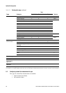
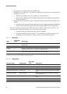
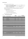
Table 8-3 Valid damping values
Process variable Valid damping values
Flow (mass and volume) 0, 0.04, 0.08, 0.16, ... 40.96
Density 0, 0.04, 0.08, 0.16, ... 40.96
Temperature 0, 0.6, 1.2, 2.4, 4.8, ... 76.8