


18 Micro Motion
®
Model 2400S Transmitters for DeviceNet
™
Connecting with ProLink II or Pocket ProLink Software
4.4 Connecting to a Model 2400S DN transmitter
To connect to the Model 2400S DN transmitter using ProLink II or Pocket ProLink, you must use a
service port connection.
4.4.1 Connection options
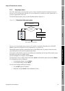
The service port can be accessed via the service port clips or the IrDA port.
The service port clips have priority over the IrDA port:
• If there is an active connection via the service port clips, access via the IrDA port is disabled.
• If there is an active connection via the IrDA port and a connection attempt is made via the
service port clips, the IrDA connection is terminated.
Additionally, access via the IrDA port may be disabled altogether. In this case, it is not available for
connections at any time. By default, access via the IrDA port is disabled. See Section 8.10.6 for more
information.
4.4.2 Service port connection parameters
The service port uses default connection parameters. Both ProLink II and Pocket ProLink
automatically use these default parameters when Protocol is set to Service Port.
Additionally, to minimize configuration requirements, the service port employs an auto-detection
scheme when responding to connection requests. The service port will accept all connection requests
within the limits described in Table 4-1. If you are connecting to the service port from another tool,
ensure that configuration parameters are set within these limits.
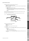
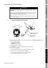
4.4.3 Connecting via the service port clips
To connect to the service port via the service port clips:
1. Attach the signal converter to the serial or USB port of your PC, using the appropriate
connectors or adapters (e.g., a 25-pin to 9-pin adapter or a USB connector).
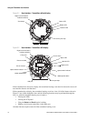
2. Remove the transmitter housing cover from the transmitter (see Section 3.3), then connect the
signal converter leads to the service port clips. See Figure 4-1.
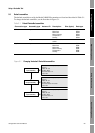
Table 4-1 Service port auto-detection limits
Parameter Option
Protocol Modbus ASCII or Modbus RTU
(1)
(1) Service port support for Modbus ASCII may be disabled. See Section 8.10.5.
Address Responds to both:
• Service port address (111)
• Configured Modbus address (default=1)
(2)
(2) See Section 8.10.4 for information on configuring the Modbus address.
Baud rate
(3)
(3) This is the baud rate between the service port and the connecting program. It is not the DeviceNet baud rate.
Standard rates between 1200 and 38,400
Stop bits 1, 2
Parity Even, odd, none