


116 Micro Motion
®
Model 2400S Transmitters for DeviceNet
™
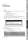
Troubleshooting
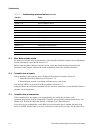
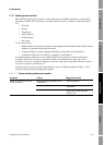
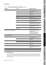
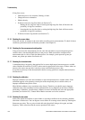
11.12 Status alarms
Status alarm codes are reported on the LCD panel (for transmitters that have a display), and status
alarms can be viewed with ProLink II or a DeviceNet tool (see Section 7.6). All possible status alarms
are listed in Table 11-2, along with the ProLink II message, possible causes, and suggested remedies.
You may find it useful to acknowledge all alarms before beginning the troubleshooting procedures.
This will remove inactive alarms from the list and allow you to focus on active alarms.
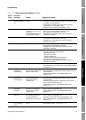
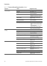
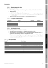
Table 11-2 Status alarms and remedies
Alarm
code
ProLink II
message Cause Suggested remedy
A001 (E)EPROM
Checksum Error
(CP)
An uncorrectable
checksum mismatch has
been detected
• Cycle power to the flowmeter.
• The flowmeter might need service. Contact Micro Motion.
See Section 11.3.
A002 RAM Error (CP) ROM checksum error or a
RAM location cannot be
written to
• Cycle power to the flowmeter.
• The flowmeter might need service. Contact Micro Motion.
See Section 11.3.
A003 Sensor Failure Continuity failure of drive
circuit, LPO, or RPO, or
LPO-RPO mismatch when
driving
• Check for slug flow. See Section 11.14.
• Check the test points. See Section 11.19.
• Check the sensor circuitry. See Section 11.20.
• Check sensor tubes for plugging.
• If the problem persists, contact Micro Motion. See
Section 11.3.
A004 Temperature
Sensor Failure
Combination of A016 and
A017
• Check the sensor RTD circuitry. See Section 11.20.
• Verify that process temperature is within range of sensor
and transmitter.
• If the problem persists, contact Micro Motion. See
Section 11.3.
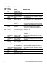
A005 Input Overrange The measured flow has
exceeded the maximum
flow rate of the sensor
(ΔT > 200 μs)
• If other alarms are present (typically, A003, A006, A008,
A102, or A105), resolve those alarm conditions first. If the
A005 alarm persists, continue with the suggestions here.
• Verify process and check for slug flow. See Section 11.14.
• Check the test points. See Section 11.19.
• Check the sensor circuitry. See Section 11.20.
• Check the sensor tubes for erosion. See Section 11.15.
• If the problem persists, contact Micro Motion. See
Section 11.3.
A006 Not Configured Combination of A020 and
A021
• Check the characterization. Specifically, verify the FCF
and K1 values. See Section 6.2.
• If the problem persists, contact Micro Motion. See
Section 11.3.
A008 Density Overrange The measured density has
exceeded 0–10 g/cm
3
• If other alarms are present (typically, A003, A006, A102, or
A105), resolve those alarm conditions first. If the A008
alarm persists, continue with the suggestions here.
• Verify process. Check for air in the flow tubes, tubes not
filled, foreign material in tubes, or coating in tubes (see
Section 11.15).
• Check for slug flow. See Section 11.14.
• Check the sensor circuitry. See Section 11.20.
• Verify calibration factors in transmitter configuration. See
Section 6.2.
• Check the test points. See Section 11.19.
• If the problem persists, contact Micro Motion. See
Section 11.3.