


128 Micro Motion
®
Model 2400S Transmitters for DeviceNet
™
Troubleshooting
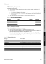
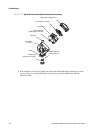
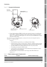
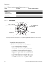
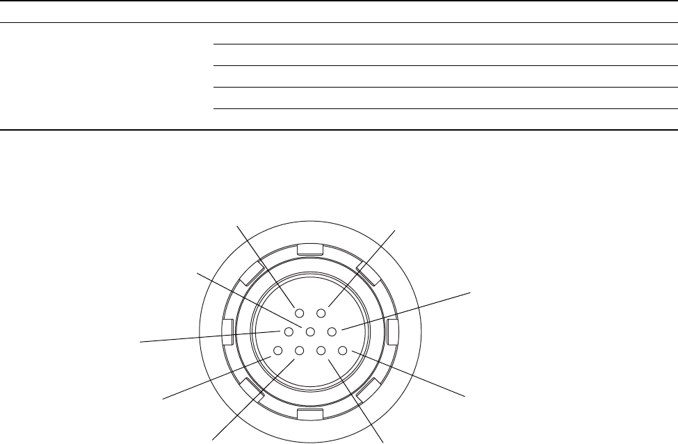
Figure 11-4 Feedthrough pins
7. Using the DMM, check each pin as follows:
a. Check between the pin and the sensor case.
b. Check between the pin and other pins as described below:
• Drive + against all other pins except Drive –
• Drive – against all other pins except Drive +
• Left pickoff + against all other pins except Left pickoff –
• Left pickoff – against all other pins except Left pickoff +
• Right pickoff + against all other pins except Right pickoff –
• Right pickoff – against all other pins except Right pickoff +
• RTD + against all other pins except RTD – and LLC/RTD
• RTD – against all other pins except RTD + and LLC/RTD
• LLC/RTD against all other pins except RTD + and RTD –
Flow tube temperature sensor RTD + and RTD – 100 Ω at 0 °C + 0.38675 Ω / °C
LLC/RTD
• T-Series sensors RTD – and composite RTD 300 Ω at 0 °C + 1.16025 Ω / °C
• CMF400 I.S. sensors RTD – and fixed resistor 39.7–42.2 Ω
• F300 sensors RTD – and fixed resistor 44.3–46.4 Ω
• All other sensors RTD – and LLC 0
(1) Actual resistance values depend on the sensor model and date of manufacture. Contact Micro Motion for more detailed data.
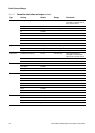
Table 11-8 Nominal resistance ranges for flowmeter circuits continued
Circuit Pin pairs Nominal resistance range
(1)
Left pickoff –
Right pickoff –
Drive – Drive +
Right pickoff +
Left pickoff +
LLC / Composite RTD /
Fixed resistor
(1)
RTD +
(1) Lead length compensator (LLC) for all sensors except T-Series, CMF400 I.S., and F300. For T-Series sensors, functions
as composite RTD. For CMF400 I.S. and F300 sensors, functions as fixed resistor.
Return for RTD, LLC,
composite RTD, or fixed resistor