


114 Micro Motion
®
Model 2400S Transmitters for DeviceNet
™
Troubleshooting
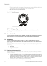
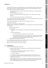
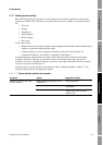
3. Visually inspect the cable and connector. Ensure that contact is good at both ends, that the pins
are not bent, the cable is not crimped, and the cable covering is intact.
4. Retry the connection using a different cable.
Figure 11-1 DeviceNet connector
11.7.2 Checking grounding
The sensor / transmitter assembly must be grounded. See your sensor installation manual for
grounding requirements and instructions.
11.8 Zero or calibration failure
If a zero or calibration procedure fails, the transmitter will send a status alarm indicating the cause of
failure. See Section 11.12 for specific remedies for status alarms indicating calibration failure.
11.9 Fault conditions
If a fault is reported, determine the exact nature of the fault by checking the status alarms (see
Section 7.6). Once you have identified the status alarm(s) associated with the fault condition, refer to
Section 11.12.
Some fault conditions can be corrected by cycling power to the transmitter. A power cycle can clear
the following:
• Zero failure
• Stopped internal totalizer
11.10 Simulation mode for process variables
Simulation allows you to define arbitrary values for mass flow, temperature, and density. Simulation
mode has several uses:
• It can help determine if a problem is located in the transmitter or elsewhere in the system. For
example, signal oscillation or noise is a common occurrence. The source could be the PLC, the
meter, improper grounding, or a number of other factors. By setting up simulation to output a
flat signal, you can determine the point at which the noise is introduced.
• It can be used to analyze system response or to tune the loop.