


Configuration and Use Manual 73
Optional Configuration
Required Configuration Optional ConfigurationUsing the TransmitterUsing a DeviceNet Tool Required Configuration Optional ConfigurationUsing the TransmitterUsing a DeviceNet Tool Required Configuration Optional ConfigurationUsing the TransmitterUsing a DeviceNet Tool Required Configuration Optional ConfigurationUsing the TransmitterUsing a DeviceNet Tool
The primary reason to disable Modbus ASCII support is to allow a wider range of Modbus addresses
for the service port.
To enable or disable Modbus ASCII support:
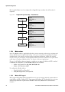
• Using ProLink II, see Figure B-2.
• Using the display menus, see Figure B-6.
8.10.6 IrDA port usage
The IrDA port on the display can be enabled or disabled. If enabled, it can be set for read-only or
read/write access.
To enable or disable the IrDA port:
• Using ProLink II, see Figure B-2.
• Using the display menus, see Figure B-6.
• Using a DeviceNet tool, see Table C-9.
To configure the IrDA port for read-only or read-write access:
• Using ProLink II, see Figure B-2.
• Using the display menus, see Figure B-6.
• Using a DeviceNet tool, see Table C-9.
8.10.7 Digital communications fault action
Digital communications fault action controls how digital communications will be affected by fault
conditions. Table 8-12 lists the options for digital communications fault action.
Note: Digital communications fault action does not affect the alarm status bits. For example, if digital
communications fault action is set to None, the alarm status bits will still be set if an alarm occurs.
See Section 7.6 for more information.
Table 8-12 Digital communications fault action options
Option
DefinitionProLink II label DeviceNet label DeviceNet code
Upscale Upscale 0 Process variables indicate the value is greater than
the upper sensor limit. Totalizers stop counting.
Downscale Downscale 1 Process variables indicate the value is less than the
lower sensor limit. Totalizers stop counting.
Zero Zero 2 Flow rates go to the value that represents zero flow.
Density and temperature go to zero. Totalizers stop
counting.
Not-A-Number
(NAN)
NAN 3 Process variables report IEEE NAN. Totalizers stop
counting.
Flow to Zero Flow goes to zero 4 Flow rates go to the value that represents zero flow;
other process variables are not affected. Totalizers
stop counting.
None (default) None 5 Process variables reported as measured.