


Configuration and Use Manual 11
Using the Transmitter User Interface
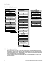
Startup Using ProLink IITransmitter User InterfaceBefore You Begin
For information on:
• Using the digital communications hardware switches, see Section 8.10.
• Using the LEDs, see Section 7.4.
• Making a service port connection, see Chapter 4.
• Using the zero button, see Section 10.5.
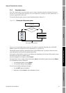
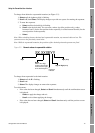
3.3 Removing and replacing the transmitter housing cover
For some procedures, you must remove the transmitter housing cover. To remove the transmitter
housing cover:
1. If the transmitter is in a Division 2 or Zone 2 area, disconnect the DeviceNet cable to remove
power from the unit.
2. Loosen the four captive screws.
3. Lift the transmitter housing cover away from the transmitter.
When replacing the transmitter housing cover, first grease the gasket, then replace the cover. Tighten
the screws so that no moisture can enter the transmitter housing.
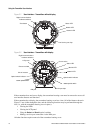
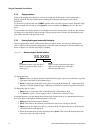
3.4 Using the optical switches
Note: This section applies only to transmitters with a display.
The
Scroll and Select optical switches are used to navigate the display menus. To activate an optical
switch, touch the lens in front of the optical switch or move your finger over the optical switch close
to the lens. There are two optical switch indicators: one for each switch. When an optical switch is
activated, the associated optical switch indicator is a solid red.
WARNING
Removing the transmitter housing cover in a Division 2 or Zone 2 area while
the transmitter is powered up can cause an explosion.
To avoid the risk of an explosion, disconnect the DeviceNet cable to remove power
from the transmitter before removing the transmitter housing cover.
CAUTION
Attempting to activate an optical switch by inserting an object into the
opening can damage the equipment.
To avoid damage to the optical switches, do not insert an object into the openings.
Use your fingers to activate the optical switches.