


Configuration and Use Manual 117
Troubleshooting
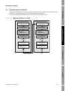
Measurement Performance DefaultsTroubleshootingCompensation
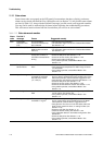
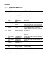
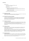
A009 Transmitter
Initializing/Warming
Up
Transmitter in power-up
mode
• Allow the flowmeter to warm up (approximately 30
seconds). The error should disappear once the flowmeter
is ready for normal operation.
• If alarm does not clear, make sure that the sensor is
completely full or completely empty.
• Check the sensor circuitry. See Section 11.20.
A010 Calibration Failure Mechanical zero: The
resulting zero was greater
than 3 μs.
Temperature/Density Cals:
many possible causes.
• If alarm appears during a transmitter zero, ensure that
there is no flow through the sensor, then retry.
• Cycle power to the flowmeter, then retry.
• If appropriate, restore the factory zero to return the
flowmeter to operation.
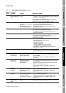
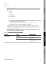
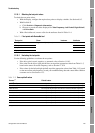
A011 Zero Too Low See A10 • Ensure that there is no flow through the sensor, then retry.
• Cycle power to the flowmeter, then retry.
• If appropriate, restore the factory zero to return the
flowmeter to operation.
A012 Zero Too High See A10 • Ensure that there is no flow through the sensor, then retry.
• Cycle power to the flowmeter, then retry.
• If appropriate, restore the factory zero to return the
flowmeter to operation.
A013 Zero Too Noisy See A10 • Remove or reduce sources of electromechanical noise,
then retry. Sources of noise include:
- Mechanical pumps
- Pipe stress at sensor
- Electrical interference
- Vibration effects from nearby machinery
• Cycle power to the flowmeter, then retry.
• If appropriate, restore the factory zero to return the
flowmeter to operation.
A014 Transmitter Failed Many possible causes • Cycle power to the flowmeter.
• The transmitter might need service. Contact Micro Motion.
See Section 11.3.
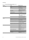
A016 Line RTD
Temperature
Out-Of-Range
The value computed for
the resistance of the Line
RTD is outside limits
• Check the sensor RTD circuitry. See Section 11.20.
• Verify that process temperature is within range of sensor
and transmitter.
• If the problem persists, contact Micro Motion. See
Section 11.3.
A017 Meter RTD
Temperature
Out-of-Range
The value computed for
the resistance of the
Meter/Case RTD is
outside limits
• Check the sensor RTD circuitry. See Section 11.20.
• Verify that process temperature is within range of sensor
and transmitter.
• Check the characterization. Specifically, verify the FCF
and K1 values. See Section 6.2.
• If the problem persists, contact Micro Motion. See
Section 11.3.
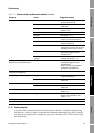
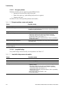
A020 Calibration Factors
Unentered
(FlowCal)
The flow calibration factor
and/or K1 has not been
entered since the last
master reset
• Check the characterization. Specifically, verify the FCF
and K1 values. See Section 6.2.
• If the problem persists, contact Micro Motion. See
Section 11.3.
A021 Incorrect Sensor
Type (K1)
The sensor is recognized
as a straight tube but the
K1 value indicates a
curved tube, or vice versa
• Check the characterization. Specifically, verify the FCF
and K1 values. See Section 6.2.
• Check the sensor RTD circuitry. See Section 11.20.
• If the problem persists, contact Micro Motion. See
Section 11.3.
A029 PIC/Daughterboard
Communication
Failure
Transmitter electronics
failure
• Cycle power to the flowmeter.
• Contact Micro Motion. See Section 11.3.
Table 11-2 Status alarms and remedies continued
Alarm
code
ProLink II
message Cause Suggested remedy