


Configuration and Use Manual 27
Required Transmitter Configuration
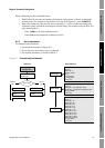
Required Configuration Optional ConfigurationUsing the TransmitterUsing a DeviceNet Tool
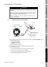
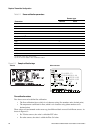
When configuring the flow calibration factor:
• With ProLink II, enter the concatenated 10-character string exactly as shown, including the
decimal points. For example, using the Flow Cal value from Figure 6-1, enter
19.0005.13.
• With a DeviceNet tool, enter the two factors separately, i.e., enter a 6-character string and a
4-character string. Include the decimal point in both strings. For example, using the Flow Cal
value from Figure 6-1:
-Enter
19.000 for the flow calibration factor.
-Enter
5.13 for the temperature coefficient for flow.
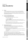
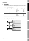
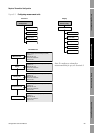
6.2.3 How to characterize
To characterize the flowmeter:
1. See the menu flowcharts in Figure 6-2.
2. Ensure that the correct sensor type is configured.
3. Set required parameters, as listed in Table 6-1.
Figure 6-2 Characterizing the flowmeter
Device
·Sensor type
Flow
T Series Config
Straight
tube
Curved
tube
Sensor type?
Density
Flow
Density
ProLink >
Configuration
Sensor type
Flow values
Class: Sensor Information Object (0x67)
Instance: 1
Attribute ID: 3
Data type: USINT
Value:
· 0: Curved tube
· 1: Straight tube
Service: Set
Density values
Class: Calibration Object (0x65)
Instance: 1
Attribute ID 7: K1
Attribute ID 8: K2
Attribute ID 9: FD
Attribute ID 12: D1
Attribute ID 13: D2
Attribute ID 17: DT
Attribute ID 18: FTG
Attribute ID 19: FFQ
Attribute ID 20: DTG
Attribute ID 21: DFQ1
Attribute ID 22: DFQ2
Data type: REAL
Service: Set
Class: Calibration Object (0x65)
Instance: 1
Attribute ID 1: Flow calibration factor
Attribute ID 2: Temperature coefficient for flow
Data type: REAL
Service: Set
DeviceNet toolProLink II