


10 Micro Motion
®
Model 2400S Transmitters for DeviceNet
™
Using the Transmitter User Interface
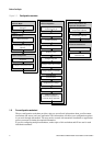
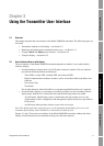
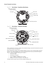
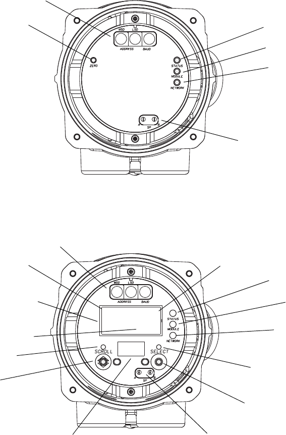
Figure 3-1 User interface – Transmitters without display
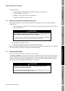
Figure 3-2 User interface – Transmitters with display
If the transmitter does not have a display, the transmitter housing cover must be removed to access all
user interface features and functions.
If the transmitter has a display, the transmitter housing cover has a lens. All of the features shown in
Figure 3-2 are visible through the lens, and the following functions may be performed through the
lens (i.e., with the transmitter housing cover in place):
• Viewing the LEDs
• Viewing the LCD panel
•Using the
Select and Scroll optical switches
• Making a service port connection via the IrDA port
All other functions require removal of the transmitter housing cover.
Status LED
Service port clips
Zero button
Module LED
Network LED
Digital communications
hardware switches
3.237
G/S
FLOW
Current value
Unit of measure
Process variable
Scroll optical switch
Select optical switch
Optical switch indicator
Status LED
Service port clips
LCD panel
Optical switch indicator
Module LED
Network LED
Digital communications
hardware switches
IrDA port