


Configuration and Use Manual 137
Menu Flowcharts
Device Profile IndexDisplay CodesMenus
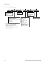
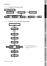
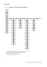
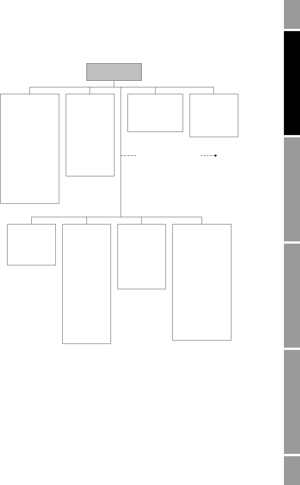
Figure B-2 ProLink II configuration menu
Flow
·Flow direction
· Flow damp
·Flow cal
· Mass flow cutoff
· Mass flow units
· Vol flow cutoff
(1)
· Vol flow units
(1)
· Vol flow type
· Std gas vol flow cutoff
(2)
· Std gas flow units
(2)
· Std gas density
(2)
Gas wizard
(2)
· Mass factor
· Dens factor
· Vol factor
Density
· Density units
· Density damping
· Slug high limit
· Slug low limit
· Slug duration
· Low density cutoff
·K1
·K2
·FD
·D1
·D2
· Temp coeff (DT)
Temperature
· Temp units
· Temp cal factor
· Temp damping
· External temperature
Pressure
·Flow factor
· Dens factor
· Cal pressure
· Pressure units
· External pressure
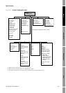
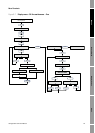
ProLink >
Configuration
Additional configuration options
Sensor
· Sensor s/n
· Sensor model num
· Sensor matl
· Liner matl
· Flange
Sensor Limits
(3)
Mass flow
· Lower sensor limit
· Upper sensor limit
· Min span
Volume flow
· Lower sensor limit
· Upper sensor limit
· Min span
Density
· Lower sensor limit
· Upper sensor limit
· Min span
Temperature
· Lower sensor limit
· Upper sensor limit
· Min span
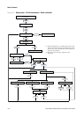
T Series
·FTG
·FFQ
·DTG
·DFQ1
·DFQ2
·K3
·D3
·D4
·K4
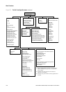
Device
·Tag
·Date
·Descriptor
· Message
· Floating pt ordering
· Add comm resp delay
· Transmitter serial #
Digital comm settings
· Fault setting
· Modbus address
· Disable Modbus ASCII
· Enable IrDA comm
· Enable write protect
IrDA port
Last measured value
timeout
(1) Displayed only if Vol Flow Type is set to Liquid Volume.
(2) Displayed only if Vol Flow Type is set to Standard Gas Volume.
(3) All values on this panel are read-only, and are displayed only for informational purposes.